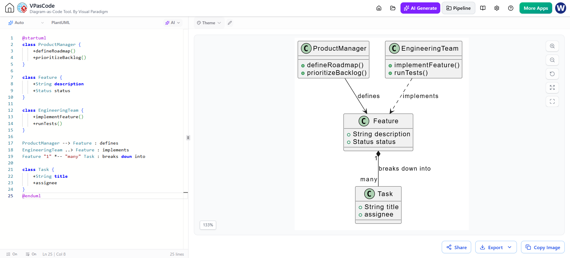
In the realm of software architecture and product development, visualizing how different teams and components interact is crucial for success. A common challenge in complex systems is mapping cross-functional responsibilities—specifically, how a Product Manager translates high-level strategy into concrete work for an Engineering Team.
This tutorial breaks down a realistic example of a Product Development Workflow using a PlantUML Class Diagram. We will explore the specific classes, their attributes and methods, and the critical relationships that bind them together.
The PlantUML Source Code
Before diving into the theory, let’s look at the raw code that generates the diagram. This script defines the structure of our system. You can copy and paste this into any PlantUML editor to visualize the relationships.
@startuml class ProductManager { +defineRoadmap() +prioritizeBacklog() }
class Feature { +String description +Status status }
class EngineeringTeam { +implementFeature() +runTests() }
ProductManager --> Feature : defines EngineeringTeam ..> Feature : implements Feature "1" -- "many" Task : breaks down into
class Task { +String title +assignee } @enduml
Deconstructing the Classes
The diagram is built around four primary classes. Each class represents a distinct role or entity within the product lifecycle.
1. ProductManager
This class represents the strategic role responsible for the vision of the product. In object-oriented terms, it is defined by specific actions (methods) it can perform:
+defineRoadmap(): A public method indicating the manager sets the long-term direction.+prioritizeBacklog(): A public method showing the manager’s duty to organize work items based on value.
2. Feature
The Feature class acts as the central artifact of the development process. It holds the data (attributes) describing the work to be done:
+String description: The textual details of what is being built.+Status status: An enumeration or object tracking the current state of the feature (e.g., “In Progress”, “Done”).
3. EngineeringTeam
Representing the execution arm, this class contains the technical methods required to turn a feature into reality:
+implementFeature(): The core coding logic.+runTests(): The quality assurance process ensuring the implementation works.
4. Task
To make work manageable, a high-level Feature is decomposed into smaller units. The Task class includes a title and an assignee, representing the individual pieces of work assigned to engineers.
Mapping Relationships and Interactions
The true power of a class diagram lies in the arrows connecting these boxes. These lines define the “verbs” of the system—how the classes interact.
Product Manager defines Feature
The solid line with an arrow pointing from ProductManager to Feature is labeled defines. This indicates a direct relationship where the manager’s output (the roadmap) creates the input for the feature.
Engineering Team implements Feature
The dashed line labeled implements connects the EngineeringTeam to the Feature. In UML, a dashed line often implies a dependency or realization. Here, it signifies that the team relies on the feature definition to execute their implementation methods.
Composition: Feature breaks down into Task
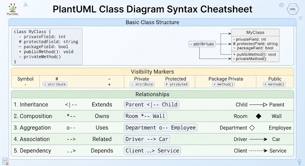
Perhaps the most critical relationship is the line connecting Feature and Task. The notation "1" -- "many" represents a Composition relationship.
- “1” (One): One specific Feature.
- “many” (Many): Can be broken down into multiple Tasks.
- Composite (Filled Diamond): This symbol suggests a strong “whole-part” relationship. If the Feature is destroyed or completed, the associated Tasks usually cease to exist in that context. It is a hierarchical breakdown of work.
Why Model This Architecture?
As noted in the context of this diagram, this modeling approach offers significant benefits for organizations like “Acme Cloud” or “Bright Labs”.
- Alignment: It provides a single source of truth for how product strategy translates into engineering tasks.
- Ownership: It clarifies who is responsible for what. The Manager defines, the Team implements, and the Tasks are assigned.
- Scalability: By visualizing the “1-to-many” relationship, teams can easily understand how a single large feature might require a complex web of smaller tasks.