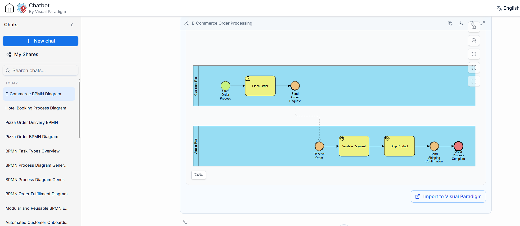
In the world of system architecture and business process management, clarity is king. One of the most powerful tools for visualizing complex interactions between different entities is BPMN (Business Process Model and Notation). In this tutorial, we will deconstruct a real-world scenario: an E-Commerce Order Processing system. By analyzing the diagram provided, we will break down how different actors communicate, how internal logic flows, and how data is managed across organizational boundaries.
Understanding the Architecture: The Two-Pool Model
Before diving into the specific symbols, it is crucial to understand the overall structure. This diagram utilizes a Two-Pool architecture. In BPMN terminology, a “Pool” represents a distinct participant or organization. Here, we see two distinct blue rectangles:
- The Customer Pool: Represents the buyer initiating the transaction.
- The Vendor Pool: Represents the seller fulfilling the request.
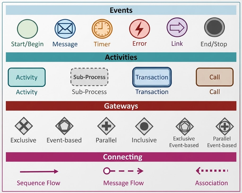
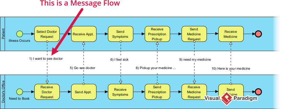
These pools act as organizational boundaries. A key rule in BPMN is that Sequence Flows (solid lines) cannot cross these boundaries. Communication between pools must happen via Message Flows (dashed lines). This separation ensures that we clearly distinguish between internal company logic and external communication.
Deep Dive: The Sequence Flow
The Sequence Flow is the backbone of any BPMN diagram. Represented by a solid line with a classic arrowhead, it dictates the order of operations within a single participant. Let’s trace the logic within the Vendor Pool, which represents the backend system’s internal workflow:
- Receive Order Event: The process begins when the vendor’s system catches an incoming event. This is depicted by the orange circle at the start of the vendor’s lane.
- Validate Payment: Once the order is received, the system must ensure funds are available. This is a task (yellow rounded rectangle) that requires specific data to proceed.
- Ship Product: If payment is valid, the process moves to the fulfillment stage.
- Send Shipping Confirmation: The final internal step involves generating a notification.
- Order Process Complete: The process ends with a red circle, indicating a successful termination.
This solid-line path represents the internal state machine of the vendor. It answers the question: “Once we have an order, what are the specific steps our system must take?”
Mastering Communication: The Message Flow
While sequence flows handle internal logic, the Message Flow handles the conversation between the Customer and the Vendor. This is depicted by a dashed line with an open arrow.
In our diagram, the communication loop is critical:
- Outbound Message: The Customer completes their “Place Order” task and triggers a message event (Send Order Request). This message travels across the pool boundary to the Vendor.
- Inbound Message: The Vendor “picks up” this message at their Receive Order event. This action kicks off the Vendor’s internal sequence flow.
- The Response: After the Vendor ships the product, they send a Shipping Confirmation message back to the Customer, completing the interaction loop.
Key Takeaway: Message Flows are asynchronous. The Customer does not wait for the Vendor to process the order in real-time; they simply send the message and wait for a response later.
Managing Data: Data Association
A robust system architecture isn’t just about steps; it’s about data. This is where Data Association comes into play. Represented by a dotted line, a Data Association links a specific data object (like a document or database record) to a task (process step).
Input: Reading Data
Consider the task Validate Payment. A computer cannot simply guess if a payment is valid; it needs information. The diagram shows a dotted line connecting a data object (likely representing the Customer Credit Record) to the task. This indicates that the task reads this data as an input to make a decision.
Output: Creating Data
Similarly, look at the Ship Product task. This task doesn’t just move a box; it generates documentation. The dotted line pointing away from the task to a data object (the Shipping Manifest) indicates that the task creates or outputs this new piece of information, which is likely stored in a database or printed for the warehouse.
Conclusion
By breaking down this E-Commerce diagram, we see a complete system architecture in action. We have defined the actors (Customer and Vendor), the internal logic (Sequence Flow), the communication protocol (Message Flow), and the data lifecycle (Data Association). Understanding these components allows developers and business analysts to design systems that are not only functional but also clear, maintainable, and easy to visualize.