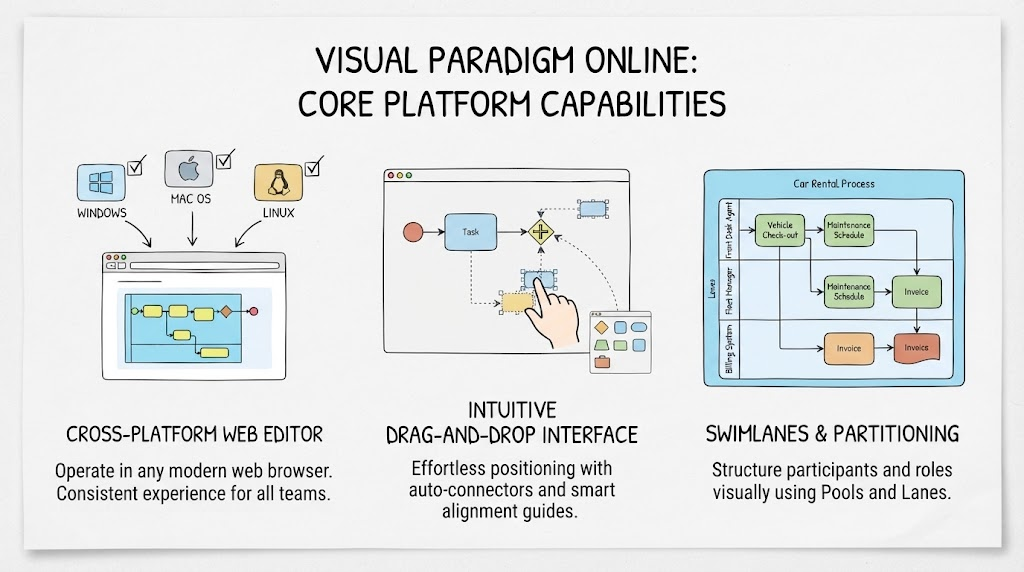
In the modern landscape of business process management, the barrier between technical modeling and collaborative execution must be seamless. This tutorial explores the core architectural capabilities and modeling concepts found in advanced cloud-based BPMN editors, specifically focusing on how platforms like Visual Paradigm Online facilitate universal access, intuitive design, and precise organizational structuring.
1. The Cross-Platform Web Editor Architecture
Traditional diagramming tools often suffer from “local installation” friction, requiring specific operating systems or heavy software downloads. The modern solution is a browser-based architecture that abstracts the underlying operating system. This approach ensures that the modeling environment remains consistent regardless of the user’s hardware.
- OS Agnosticism: The editor operates seamlessly within any modern web browser, effectively eliminating OS compatibility issues. Whether a team member is using Windows, Mac OS, or Linux, they access the exact same feature-rich workspace.
- Consistent Collaboration: By centralizing the workspace in the cloud, teams eliminate “it works on my machine” discrepancies. Updates and changes are synchronized in real-time, ensuring everyone is working from the same version of the truth.
2. The Intuitive Drag-and-Drop Interface
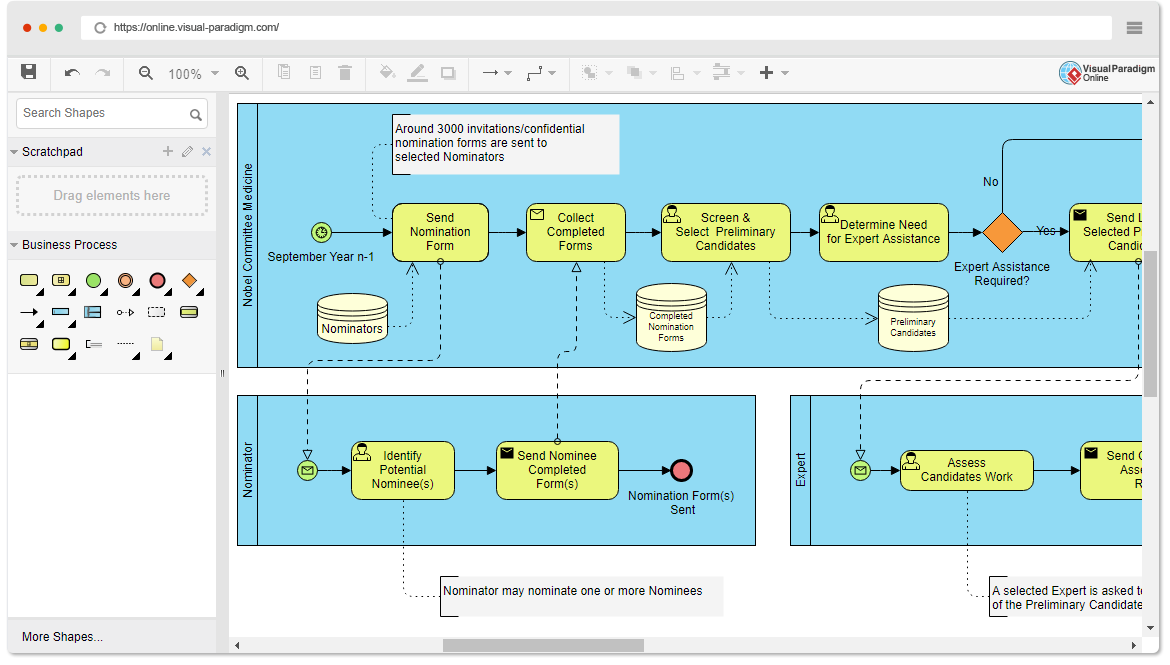
A hallmark of an effective Business Process Modeling Notation (BPMN) tool is the quality of its canvas. The user experience (UX) must prioritize the modeling of logic over the aesthetics of formatting. Modern editors achieve this through responsive interfaces equipped with intelligent assistance features.
Smart Canvas Features
When constructing a process map, the system employs specific technical aids to maintain diagram integrity:
- Smart Alignment Guides: These visual cues help users position elements perfectly relative to one another without manual pixel-perfect adjustment.
- Auto-Connectors: The system automatically detects relationships between elements, allowing users to effortlessly position standard BPMN elements, artifacts, and flow connectors.
- Focus on Logic: By automating the formatting, the user can dedicate their cognitive load to the process logic rather than the visual structure.
3. Swimlanes and Partitioning
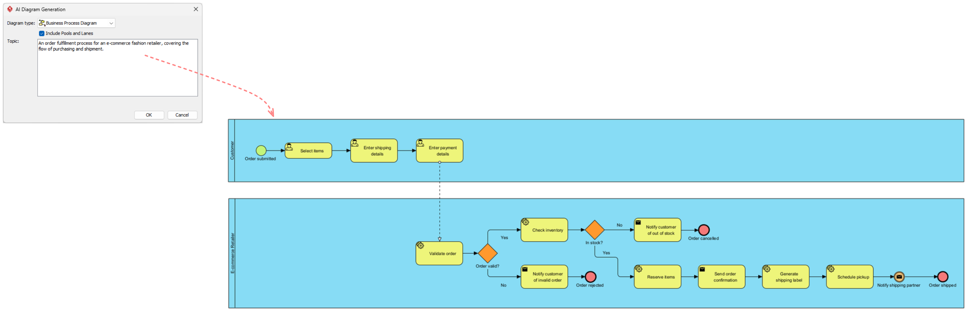
Complex business processes rarely occur in a vacuum; they involve multiple stakeholders, departments, and external systems. To model this reality accurately, BPMN tools provide native support for Swimlanes (also known as Pools and Lanes). This partitioning is essential for distinguishing between different actors in a process.
By structuring the diagram into distinct zones, you can clearly delegate operational roles and ensure that responsibility and handoffs are visually unambiguous. This is critical for identifying bottlenecks and defining Service Level Agreements (SLAs) between different entities.
Key Concept: Pools vs. Lanes
Understanding the hierarchy of swimlanes is fundamental to advanced BPMN modeling. Here is the technical breakdown:
- The Pool: Represents a major participant in the process. This is the highest level of partitioning.
- Example: “Customer,” “Fulfillment Department,” or “Rental Agency.”
- Technical Note: A pool can contain one or more lanes, or it can exist as a single block representing an entire organization.
- The Lane: A sub-partition within a pool used to organize activities by role, department, or system.
- Example: “Sales Rep,” “Warehouse Manager,” or “ERP System.”
- Technical Note: Lanes allow you to map the flow of information and tasks between specific internal actors within a single major participant.
Case Study: The Car Rental Process
To visualize this architecture, consider a Car Rental Process modeled within a Pool named “Rental Agency.” Inside this pool, the process is divided into specific Lanes to handle distinct responsibilities:
- Lane: Front Desk Agent – Responsible for the initial “Vehicle Check-out.”
- Lane: Fleet Manager – Handles “Maintenance Scheduling” triggered by the check-out.
- Lane: Billing System – An automated system lane responsible for “Invoice Generation.”
This structure allows a stakeholder to instantly see that the Fleet Manager is notified when the Front Desk Agent completes a task, and that the Billing System is triggered by the completion of the rental event. It transforms a complex web of text into a clear, navigable map of organizational responsibility.