


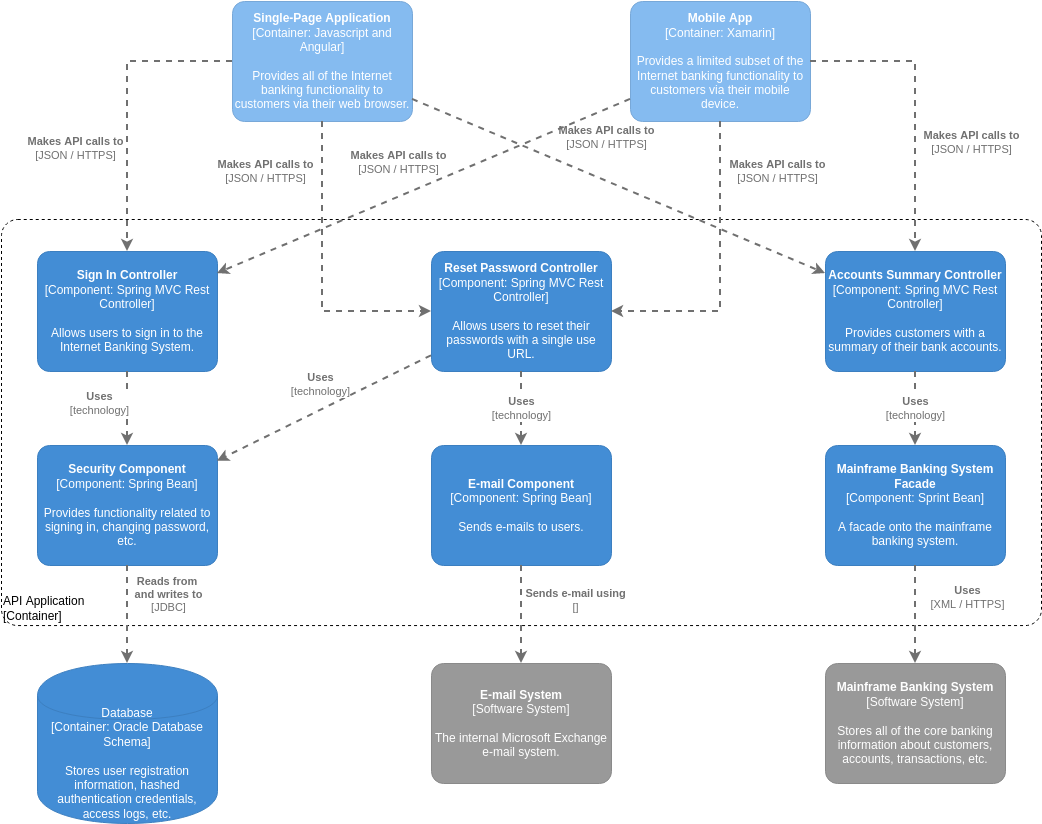
Visualizing complex software systems can be a daunting task, but the C4 model provides a structured, hierarchical approach to make architecture clear for everyone involved. In this tutorial, we will walk through a specific C4 Component Diagram representing a secure Internet Banking System. This diagram serves as a perfect example of how to document the internal logic of a backend system, its dependencies, and its interactions with external users.
By understanding this diagram, you will learn how to break down a monolithic system into manageable components, identify key technologies (like Spring MVC), and map out data flows between databases and legacy systems.
Understanding the C4 Model: Where This Diagram Fits
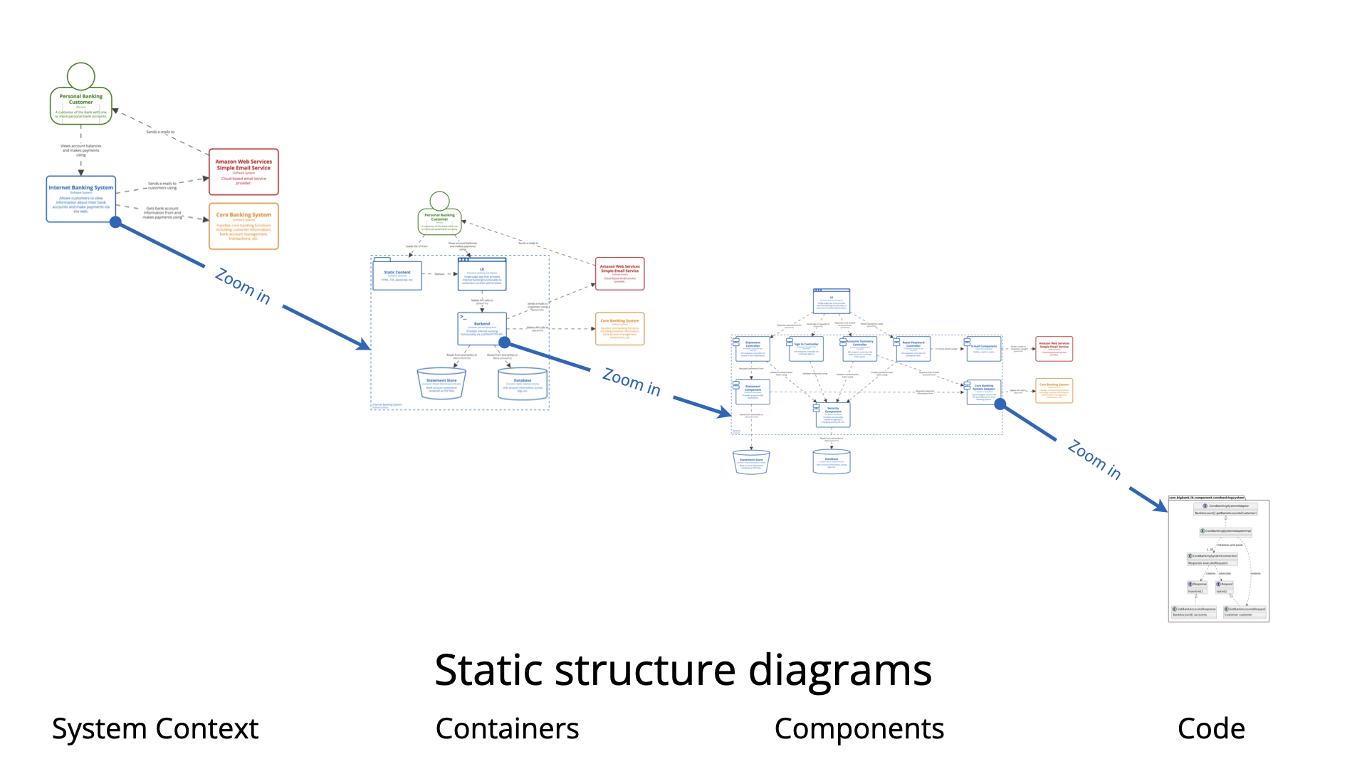
The C4 model consists of four levels: Context, Container, Component, and Code. The diagram provided is a Level 3: Component Diagram. It zooms in on a single container—the API Application—to show how its internal parts work together.
- Level 1 (Context): Shows the system in relation to users and external systems (not shown here).
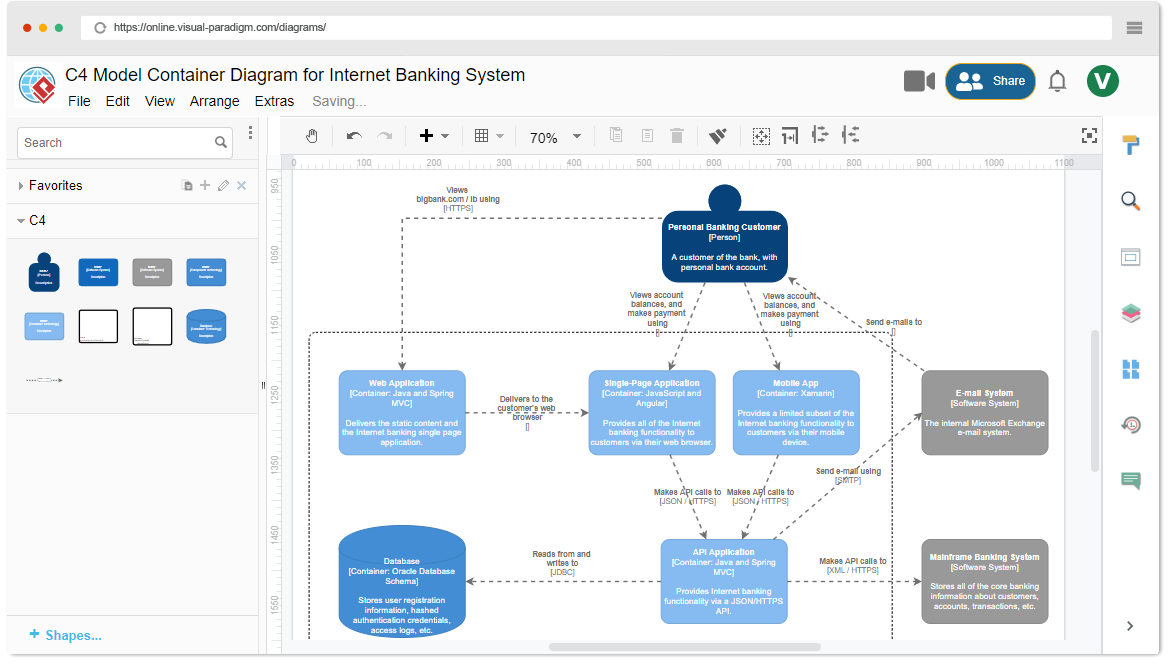
- Level 2 (Container): Shows the high-level building blocks (e.g., Web App, Mobile App, API). This is the dotted box in the center.
- Level 3 (Component): (This Diagram) Shows the distinct parts inside a container and their responsibilities.
- Level 4 (Code): Shows the class structure (not applicable here).

Deconstructing the External Interactions
At the very top of the diagram, we see the Client Applications that interact with our system. These are the entry points for the user.
- Single-Page Application (SPA): Built with JavaScript and Angular. This provides the full internet banking functionality to customers via a web browser.
- Mobile App: Built with Xamarin. This provides a limited subset of functionality for mobile users.
Connection Logic: Notice the dashed lines connecting these apps to the backend. The label Makes API calls to [JSON / HTTPS] indicates that these clients communicate with the API via standard RESTful web services using JSON data over secure HTTPS connections.
The Core: The API Application Container
The large dotted rectangle in the middle represents the API Application Container. This is the backend server responsible for handling business logic. Inside this container, we see three primary “Controller” components that handle specific user requests:
1. Sign In Controller
This component is a Spring MVC Rest Controller. Its sole responsibility is to authenticate users. It allows customers to sign in to the Internet Banking System securely.
2. Reset Password Controller
Also a Spring MVC Rest Controller, this component handles password recovery. It allows users to reset their credentials using a single-use URL, a critical security feature.
3. Accounts Summary Controller
This Spring MVC Rest Controller is responsible for data retrieval. It provides customers with a high-level summary of their bank accounts.
Supporting Components and Internal Logic
Controllers rarely work alone. They delegate specific tasks to supporting components. This separation of concerns keeps the code clean and maintainable.
The Security Component
Both the Sign In and Reset Password controllers rely on the Security Component. Labeled as a Spring Bean, this component encapsulates all logic related to authentication, password hashing, and session management. The arrow labeled Uses [technology] indicates a dependency.
The E-mail Component
The E-mail Component (another Spring Bean) handles communication. It sends transactional emails to users, such as the password reset link. It does not define how the email is sent, only that it is sent.
The Mainframe Banking System Facade
This is a classic design pattern implementation. The Mainframe Banking System Facade acts as a wrapper or proxy. It simplifies the interaction with the legacy Mainframe Banking System. Instead of the API talking directly to the complex Mainframe, it talks to the Facade, which handles the translation.
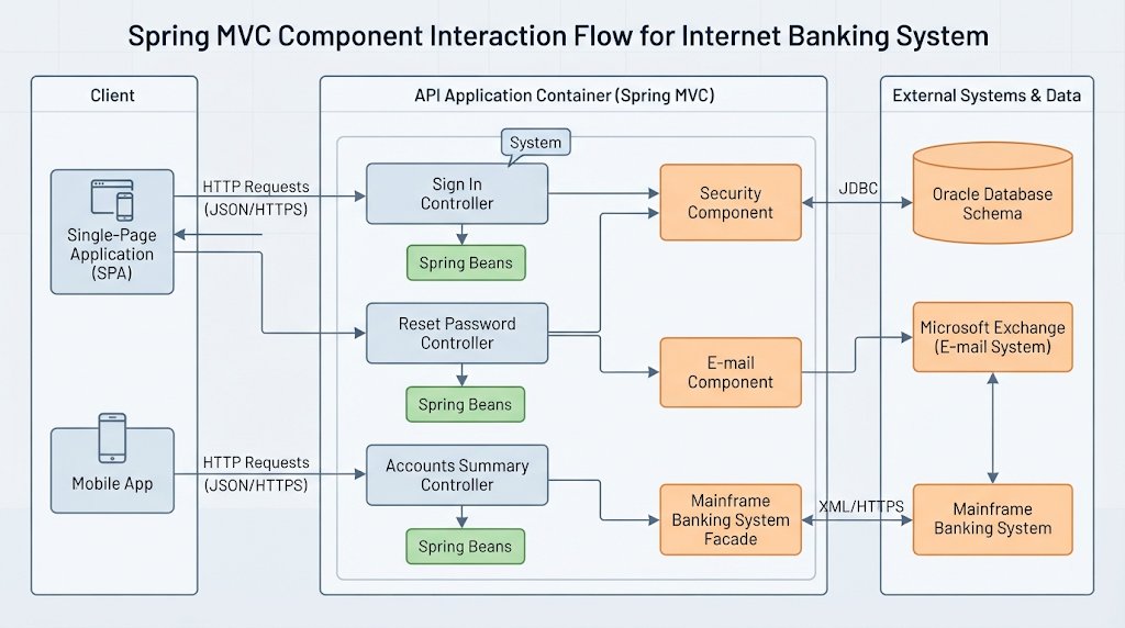
External Systems and Data Storage
Finally, the diagram shows what sits outside the API Application but is essential for its operation. These are the supporting systems at the bottom.
- Database (Oracle Database Schema): The Security Component reads from and writes to this database using JDBC (Java Database Connectivity). It stores user registration info, hashed credentials, and access logs.
- E-mail System (Microsoft Exchange): The E-mail Component sends emails using this internal system.
- Mainframe Banking System: The Mainframe Facade communicates with this legacy system using XML / HTTPS. This system stores the “source of truth” for customer accounts and transactions.
Key Takeaways for Developers
By modeling your system this way, you gain several advantages:
- Clarity: You can instantly see that the API uses Spring MVC for controllers and Spring Beans for logic.
- Dependency Management: It becomes obvious that if the Database goes down, the Sign In functionality is broken.
- Technology Stack Visibility: Stakeholders can see that the backend relies on Oracle and a Mainframe, which might influence future migration plans.
Whether you are using Visual Paradigm’s AI tools or drawing by hand, adhering to the C4 model ensures your architecture documentation remains readable, regardless of how complex your software becomes.
Related posts:
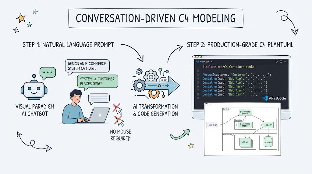 Master Conversation-Driven C4 Modeling with AI
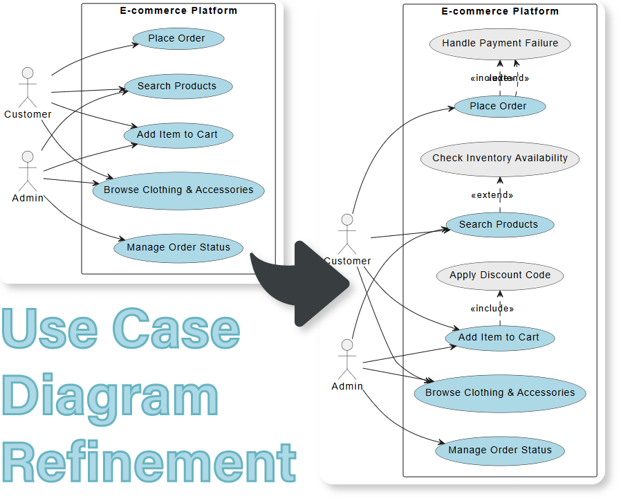 Refining Use Case Diagrams: From Basic to Advanced E-commerce Models
 Mastering Software Architecture: A Comprehensive Guide to the C4 Model and Visual Paradigm
 Mastering the C4 Model: A Step-by-Step Guide to the Container Diagram for an Internet Banking System