In the realm of IT Service Management (ITSM), clarity is king. Ambiguity in how a support ticket is handled can lead to delays, frustrated employees, and technical debt. This tutorial breaks down a sophisticated Business Process Diagram (BPMN 2.0) created in Visual Paradigm, illustrating a standard “IT Service Request Management” workflow.
By examining the screenshot provided, we will explore how to model complex organizational interactions, define decision logic, and visualize the handover of responsibilities between different departments. Whether you are a business analyst, an IT manager, or a student of system architecture, understanding this diagram is crucial for streamlining operational efficiency.
1. The Power of Swimlanes: Defining “Who” Does “What”
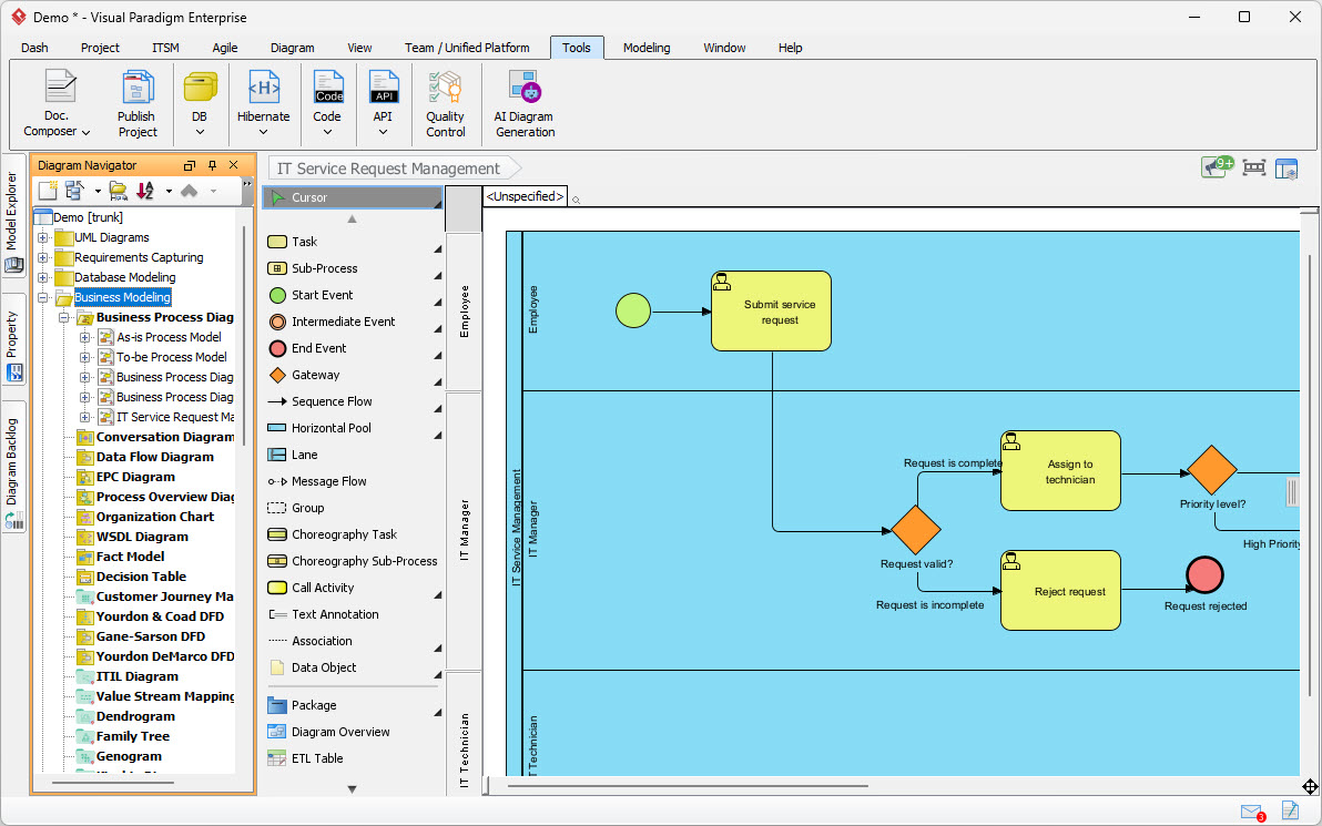
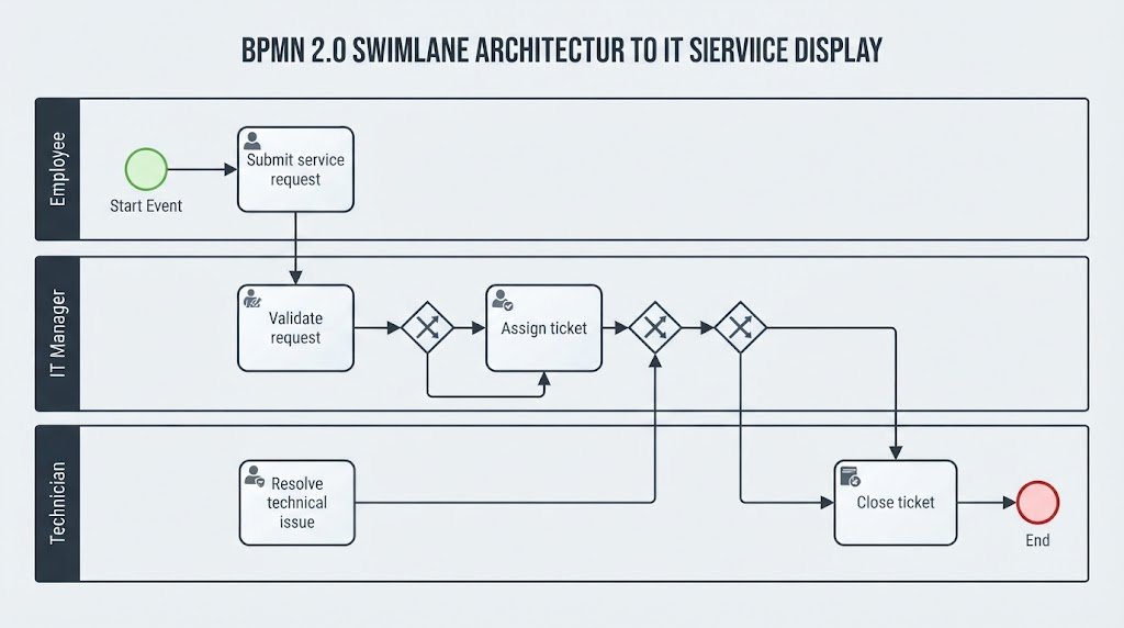
The most striking feature of this diagram is its use of Swimlanes. In BPMN, swimlanes are horizontal or vertical areas that partition the diagram to show which actor is responsible for specific tasks. This visual separation is vital for preventing role confusion.
In this specific architecture, we see three distinct lanes:
- Employee Lane (Top): This represents the initiator of the process. The actions here are low-level and trigger events, such as the initial submission of a request.
- IT Manager Lane (Middle): This lane acts as the control center. It contains the logic and decision-making nodes. The manager validates the quality of the request before it proceeds to execution.
- Technician Lane (Bottom): This lane represents the execution layer. Once a request is validated and assigned, the work is handed off here for actual technical resolution.
2. Step-by-Step Process Walkthrough
Let us trace the flow of data and tasks through the diagram, starting from the top left and moving right.
Step 1: Initiation (The Start Event)
The process begins with a green circle, known as a Start Event. In this model, the trigger is an employee deciding they need IT support. This immediately transitions to the first task.
Step 2: The Request Task
The yellow rectangle labeled “Submit service request” is a standard User Task. This implies that a human actor (the Employee) must manually input data, likely into a portal or ticketing system, to move the process forward.
Step 3: The Validation Gateway
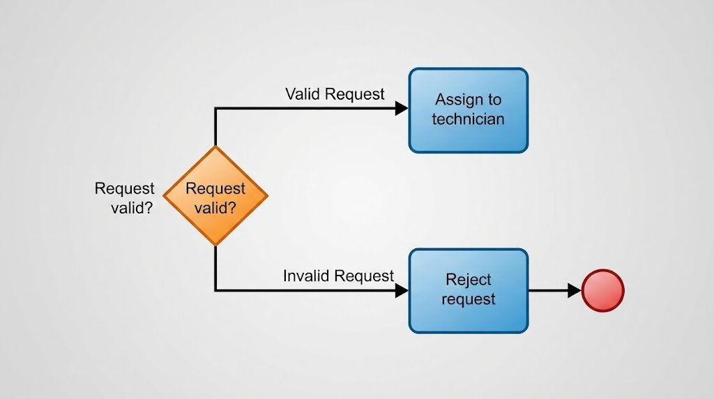
This is the critical pivot point of the diagram. The arrow from the submission task leads to an orange diamond labeled “Request valid?”. In BPMN terminology, this is an Exclusive Gateway. It represents a decision point where the flow splits into two mutually exclusive paths based on a condition.
- Path A (Request is incomplete): If the manager determines the request is missing information or invalid, the flow moves to the “Reject request” task. This ends with a red circle, a End Event, signifying the termination of the workflow.
- Path B (Request is complete): If the validation passes, the request is routed to the “Assign to technician” task.
3. Advanced Logic: Prioritization
Once the request is assigned to the technician, the diagram shows a second decision point: a second orange diamond labeled “Priority level?”. This demonstrates that the workflow is not linear; it branches based on dynamic data.
Although the diagram is cut off slightly, we can see a path labeled “High Priority” leading to a grayed-out task. This indicates that the system (or the technician) must evaluate the urgency of the ticket. This is a classic example of dynamic routing, where high-priority issues might bypass standard queues or trigger specific escalation protocols.
4. Understanding the Visual Paradigm Interface
For those looking to recreate this architecture, the screenshot reveals the power of the Visual Paradigm toolset. Notice the palette on the left side of the screen:
- Task & Sub-Process: The yellow icons used for actions.
- Gateways: The orange diamond used for logic branching.
- Lane: The blue container used to organize the actors.
- Sequence Flow: The solid arrows connecting the elements, defining the order of operations.
Conclusion
This diagram is more than just a picture; it is a formal specification of a business rule set. By modeling the “IT Service Request Management” process, the organization ensures that:
- No request enters the system without validation.
- Invalid requests are handled gracefully (rejection) rather than clogging the technician’s queue.
- Priorities are explicitly defined to ensure critical issues are resolved first.
Mastering these modeling concepts allows you to bridge the gap between abstract business requirements and concrete technical implementation.