In the world of Business Process Model and Notation (BPMN) and system architecture, clarity is king. A well-designed diagram acts as a universal language, allowing stakeholders to understand complex workflows instantly. However, when diagrams become a tangled mess of crossing lines, they transform into the dreaded “Spaghetti Model.” This tutorial explores why crossing flow lines are detrimental to system design, illustrates the real-world impact using an Agile usage case, and demonstrates how to maintain clean, readable architectures using tools like Visual Paradigm.
The Mistake: Understanding Crossing Flow Lines
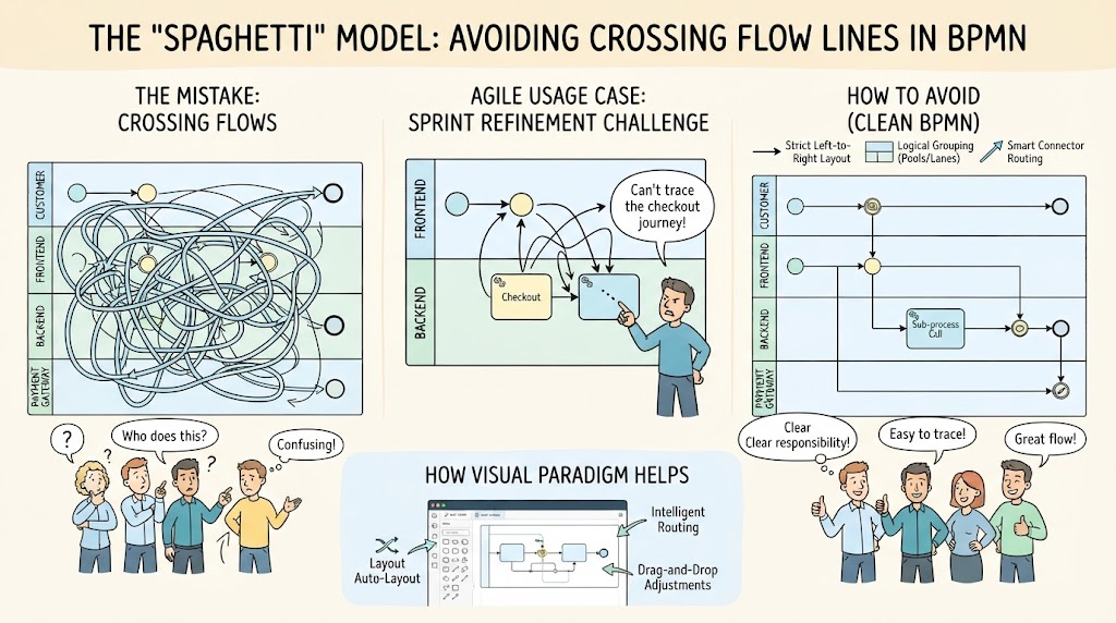
The most common error in process modeling is connecting sequence flows haphazardly across the diagram. When lines cross over one another multiple times without a clear pattern, they create a visual noise that makes the process impossible to follow. This is known as the “Spaghetti” model.
Consider a standard BPMN diagram with Pools and Lanes. These lanes represent different responsibilities (e.g., Customer, Frontend, Backend, Payment Gateway). When a developer or analyst draws a flow line from a task in the “Frontend” lane that stretches all the way across the diagram to a “Backend” lane, crossing over other lines in the process, the cognitive load on the reader skyrockets. The eye gets lost in the tangle, making it difficult to trace the sequence of events.
- The Result: A diagram that looks like a bowl of uncooked spaghetti.
- The Consequence: Stakeholders cannot verify logic, and developers struggle to implement requirements.
Agile Usage Case: The Sprint Refinement Challenge
Let’s look at a practical scenario where this modeling mistake occurs in an Agile environment. Imagine a team is working on a new Checkout Feature for an e-commerce application.
The Scenario
During a Sprint Refinement Session, the team attempts to map the user journey. The diagram includes lanes for the Customer, Frontend, Backend, and Payment Gateway.
The Problem
Because the flow lines were drawn without a strict layout strategy, lines from the “Checkout” task in the Frontend lane cross over the “Payment Gateway” lane and intersect with logic for “User Authentication” in the Backend lane. A developer points at the diagram and says, “I can’t trace the checkout journey!”
This confusion leads to:
- Ambiguity: It is unclear which lane is responsible for the next step.
- Errors: Developers might implement logic in the wrong service layer.
- Delays: Time is wasted debating the flow instead of building the feature.
How to Avoid It: Best Practices for Clean BPMN
To maintain a professional and readable system architecture, you must adhere to specific structural rules. Here is how to prevent the spaghetti model:
1. Follow a Strict Layout Strategy
Always adhere to a Left-to-Right or Top-to-Bottom layout. This natural reading order helps the eye track the flow of data and control. Avoid looping lines back to the start unless absolutely necessary, and even then, do so neatly.
2. Utilize Pools and Lanes for Logical Grouping
Group related responsibilities logically. Do not force a single process to span across unrelated lanes without a clear reason.
- Customer Lane: Initiates the request.
- Frontend Lane: Handles UI logic and input validation.
- Backend Lane: Processes business rules.
- Payment Gateway Lane: Handles external transactions.
3. Use Intermediate Events and Sub-processes
If a flow must cross lanes, do not stretch a single line across the entire canvas. Instead, use Intermediate Events (like Message Events) or break the flow into Sub-processes. This acts as a “handshake” point, clearly defining where one process ends and another begins, reducing visual clutter.
How Visual Paradigm Helps
Manual diagramming is prone to human error, but modern modeling tools offer powerful features to automate layout and prevent the spaghetti model. Visual Paradigm, for instance, provides specific capabilities to ensure your diagrams remain clean:
Intelligent Routing and Auto-Layout
Visual Paradigm’s Auto-Layout features automatically route lines to avoid overlaps. When you add a new task or connection, the tool calculates the optimal path, ensuring lines do not cross unnecessarily.
Drag-and-Drop Adjustments
The intuitive Drag-and-Drop interface is more than just moving shapes. When you move a task, the connected flows adjust intelligently. The connectors “stretch” and “bend” to maintain their logical path without creating new tangles, maintaining a clean, “spaghetti-free” structure.
The Outcome
By leveraging these tools and adhering to the rules of strict layout and logical grouping, your diagrams will transform from confusing messes into clear, professional blueprints. As shown in the comparison, a clean model results in clear responsibility, easy tracing, and a great flow for the entire development team.