In the realm of software engineering, the most significant challenge teams face is bridging the gap between abstract requirements and concrete code. How do you translate a product manager’s vision or a user’s need into a functioning application? The answer lies in effective modeling, specifically using the Unified Modeling Language (UML).
This tutorial explores two foundational pillars of Object-Oriented Design (OOD): the UML Class Diagram and the UML Object Diagram. We will walk through how these diagrams function as the “blueprint” and the “snapshot” of a system, using a practical e-commerce example to illustrate the journey from design to implementation.
The Journey: From Requirements to Reality
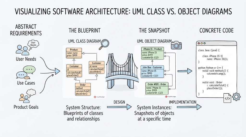
Before diving into the diagrams, it is essential to understand the workflow they represent. Software development is rarely a linear path; it is a transformation process:
- Abstract Requirements: The process begins with User Needs, Use Cases, and Product Goals. These are the “what” and “why” of the system.
- The Blueprint (Design): We translate these requirements into structural models. This is where the Class Diagram comes into play.
- The Snapshot (Implementation): We create specific instances of our design to verify logic. This is the domain of the Object Diagram.
- Concrete Code: Finally, the validated models are translated into actual programming languages like Java, Python, or C++.
The Blueprint: UML Class Diagrams
Imagine you are an architect building a bridge. You wouldn’t start by laying down specific bricks; you would start with a blueprint. In software, the Class Diagram is that blueprint.
A Class Diagram defines the static structure of a system. It shows the classes, their attributes, methods, and the relationships among objects. It answers the question: “What are the components of my system and how do they relate?”
Key Components of a Class
In our e-commerce example, the diagram highlights three critical classes:
- Product: Represents items for sale. It contains attributes like
nameandprice. - Customer: Represents the buyer. It holds an
idandname. - Order: Represents the transaction. It includes a
method(logic) tocalculateTotal()andplaceOrder().
Relationships
Class diagrams use arrows to denote relationships. Notice how the Order class points to Product and Customer. This signifies that an Order is dependent on a Product and a Customer. This structural definition allows developers to understand the system’s architecture before writing a single line of code.
The Snapshot: UML Object Diagrams
If the Class Diagram is the blueprint, the Object Diagram is a snapshot of the bridge at a specific moment in time. It shows a specific instance of the structure defined in the class diagram. It answers the question: “What does the system look like right now with real data?”
Object diagrams are crucial for debugging and understanding the dynamic behavior of a system at a particular point in a use case. They visualize actual data values rather than abstract data types.
Visualizing the Snapshot
Looking at our e-commerce scenario, the Object Diagram (the “snapshot”) shows specific instances:
- Instance 1: An object of type
iPhone 15 : Productwith a specific price of$999. - Instance 2: An object of type
John Doe : Customerwith a specific IDC123. - Instance 3: An object of type
Order #101 : Orderthat links the specific phone and the specific customer.
This visualization confirms that Order #101 is validly structured because it references existing instances of a Product and a Customer. This is the “Concrete Code” preparation phase—ensuring the logic holds up when real data is plugged in.
Bridging the Gap with Visual Paradigm
To create these diagrams effectively, many professionals rely on tools like Visual Paradigm. This software allows developers to model complex systems visually, translating abstract requirements into tangible specifications.
By using a modeling tool, teams can:
- Visualize Architecture: See the big picture of how
ProductandCustomerinteract. - Validate Logic: Create snapshots (Object Diagrams) to ensure that the relationships (like placing an order) make sense with actual data.
- Generate Code: Many tools can even reverse-engineer code from these diagrams or generate skeleton code for Java, Python, or C++ directly from the Class definitions.
Conclusion
Whether you are an experienced Product Manager or a developer refining your architectural skills, understanding the distinction between Class and Object diagrams is essential. The Class Diagram provides the System Structure—the blueprints. The Object Diagram provides the System Instances—the snapshots.
By mastering these visual languages, you ensure that your software is not just written, but designed robustly and scalably from the very first requirement.