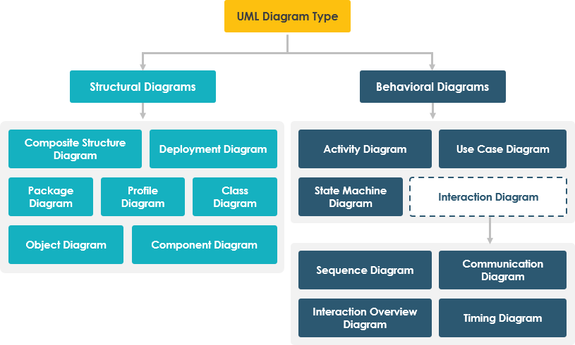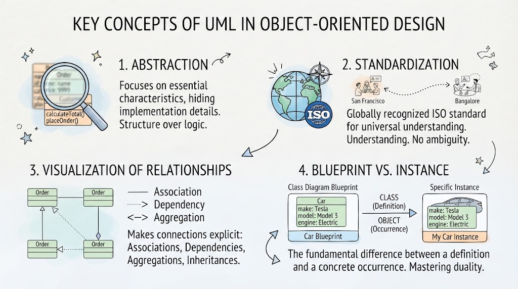
Before diving into the complex syntax of class diagrams or state machines, it is essential to understand the philosophical and structural bedrock that makes Unified Modeling Language (UML) the industry standard for software architecture. UML is not merely a drawing tool; it is a language of abstraction designed to bridge the gap between human thought and machine implementation.
This tutorial explores the four fundamental pillars that underpin effective UML modeling: Abstraction, Standardization, Visualization of Relationships, and the critical distinction between Blueprints and Instances.
1. The Power of Abstraction
In the realm of software engineering, complexity is the enemy. The primary utility of UML lies in its ability to perform Abstraction. When a developer writes code, they are often bogged down in the minutiae of implementation details—variable names, specific algorithms, and syntax quirks. UML allows teams to step back and focus on the essential characteristics of a system.
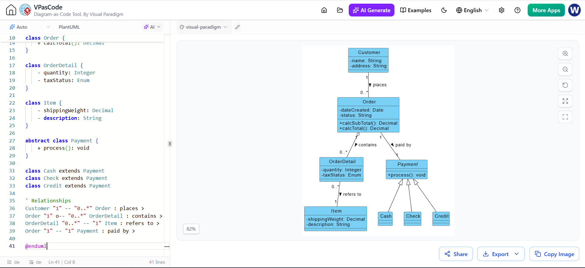
When you create a UML Class Diagram, you are intentionally ignoring the implementation logic. You are not showing if statements or while loops; you are showing structure. This focus on structure over logic enables stakeholders to grasp the “big picture” of the system without getting lost in the weeds of the code.
2. The Necessity of Standardization
Software development is rarely a solitary activity; it is a collaborative effort that often spans across time zones and cultures. This is where Standardization becomes vital. Because UML is a globally recognized ISO standard, it serves as a lingua franca for developers.
Consider a scenario where a system architect in San Francisco creates a diagram and a development team in Bangalore executes the code. Without a standard like UML, the diagram might be interpreted differently by each team, leading to ambiguity and costly errors. With UML, the diagram created in San Francisco is understood by the team in Bangalore without ambiguity, ensuring that the architectural vision is preserved across the entire development lifecycle.
3. Visualization of Relationships
One of the most significant limitations of raw source code is how it hides the connections between components. In a file-based structure, relationships are often buried within import statements or interface declarations. UML changes the paradigm by making these connections Explicit and Visual.
A well-drawn UML diagram reveals the dynamic interplay of the system. It explicitly maps out:
- Associations: The fundamental links between objects.
- Dependencies: How one element relies on another to function.
- Aggregations: “Has-a” relationships where parts can exist independently.
- Inheritances: The hierarchy of classes and shared behaviors.
By visualizing these relationships, architects can spot potential bottlenecks, circular dependencies, or design flaws before a single line of code is written.
4. Blueprint vs. Instance: The Duality of Modeling
Perhaps the most crucial concept for a new UML practitioner to master is the distinction between a Definition (Class) and a Specific Occurrence (Object). This is the difference between a blueprint and a physical house.
Understanding this duality is key to effective modeling:
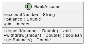
- The Class (The Blueprint): This is the template. It defines the properties (like
make,model) and behaviors that an entity possesses, but it does not exist in memory as a running entity. It is a static definition. - The Object (The Instance): This is a concrete realization of that definition. It is a specific occurrence in time and space. For example, a
Carclass defines what a car is, but a specificMy Car Instancewith the make “Tesla” and engine “Electric” is an actual object running in your system.
Mastering the ability to toggle between these two views allows you to design flexible systems. You design the blueprint to be reusable, while understanding that the runtime environment is a collection of unique instances interacting with one another.