In the world of software engineering and system architecture, clarity is king. When designing complex systems like a Smart Home network, developers must distinguish between the rules of the system and the state of the system at any given moment. This tutorial breaks down the fundamental distinction between a Class Diagram and an Object Diagram, using a practical “Smart Home” scenario to visualize how code transforms into reality.
1. The Foundation: The Class Diagram (The Blueprint)
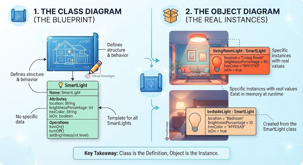
Imagine you are an architect designing a new house. Before a single brick is laid, you rely on a set of blueprints. In Object-Oriented Programming (OOP), the Class Diagram serves as this blueprint. It defines the structure and behavior of a system without involving specific data.
Defining the SmartLight Class
Let’s look at the left side of our diagram, labeled 1. The Class Diagram. Here, we define a template called SmartLight. This template dictates what a smart light is and what it can do.
- Attributes (The Properties): The class defines the data fields that every smart light will possess.
location(String): Where is the light?brightnessPercentage(int): How bright is it?hexColor(String): What color is the light?isOn(boolean): Is the power active?
- Operations (The Methods): These are the actions the light can perform.
turnOn(): Activates the device.turnOff(): Deactivates the device.setBrightness(int level): Adjusts the intensity.
Crucially, notice that the Class Diagram does not contain specific data. It defines that a light has a color, but it doesn’t specify which color yet. This is the definition phase.
2. The Reality: The Object Diagram (The Real Instances)
If the Class Diagram is the blueprint, the Object Diagram represents the physical house built from that plan. In programming terms, this is the runtime state of your application. Objects are concrete instances created from the class template.
Instantiating Reality
On the right side of our diagram, labeled 2. The Object Diagram, we see two distinct objects derived from the SmartLight class. These objects exist in memory simultaneously with unique state values.
Instance 1: livingRoomLight
This object represents the smart light installed in the living room. Unlike the blueprint, this object holds real values:
- Location: “Living Room”
- Brightness: 80%
- Color: “#FF5733” (Orange)
- Status:
true(On)
Instance 2: bedsideLight
This object represents the lamp next to the bed. It is a separate entity with its own memory footprint:
- Location: “Bedroom”
- Brightness: 10%
- Color: “#FFD1A9” (Soft Peach)
- Status:
true(On)
3. Key Takeaway: The Relationship Between Definition and Instance
The visual flow in the diagram illustrates the lifecycle of software objects. The arrow flowing from the blueprint to the scene signifies Instantiation.
- The Class is the Definition: It is a static structure that provides the logic and the container for data. It is “Template for all SmartLights.”
- The Object is the Instance: It is the dynamic, active entity that exists in memory at runtime. It holds the “Specific instances with real values.”
Understanding this distinction is vital for system architects. When you design a system, you define the classes first to ensure consistency. When you run the system, you manage the objects to handle the specific, changing data of the real world.