


In the world of software engineering and system design, clarity is king. When developers, architects, and stakeholders collaborate on complex systems, they need a common language to describe the structure of that system. Enter the Class Diagram—the backbone of the Unified Modeling Language (UML) and the most popular diagram type used by the object-oriented community.
This tutorial explores the fundamental concepts of Class and Object diagrams, breaking down how they map abstract logic to concrete code, and how modern tooling can streamline this entire workflow.
Understanding the Class Diagram
A class diagram is often described as the blueprint of a software application. It provides the static view of a system, meaning it captures the structure rather than the behavior or flow. Unlike other diagrams that might show how data moves (like Sequence or Activity diagrams), a class diagram focuses on what exists within the system.
Core Components
At its heart, a class diagram is built upon two main pillars:
- Classes: These are the building blocks of the system, representing a category of objects that share the same attributes and behaviors.
- Relationships: These define how classes interact, inherit, or depend on one another.
Technically, a single class diagram typically describes a specific aspect of the system. When you collect multiple class diagrams together, they form a comprehensive representation of the entire system architecture.
The “Object-Oriented” Advantage
Why are class diagrams so ubiquitous? The answer lies in their direct mapping capabilities. Class diagrams are the only UML diagrams that can be mapped directly to object-oriented programming languages (like Java, C#, or Python). This unique feature bridges the gap between design and implementation, making them indispensable for developers.
Diving into a Class Diagram Example
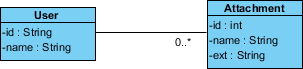
To truly understand these concepts, let’s analyze a concrete scenario involving a User and an Attachment. Imagine a system where users can upload files to a profile.
The User Class
This class represents the actor in our system. It defines the data associated with a person:
-id : String: A unique identifier for the user.-name : String: The display name of the user.
The Attachment Class
This class represents the data object (the file) being uploaded:
-id : int: A numeric identifier for the file.-name : String: The filename.-ext : String: The file extension (e.g., .pdf, .jpg).
The Association and Multiplicity
The relationship between these two classes is defined by a line connecting them. This is called an Association. However, the line alone isn’t enough; we need to define the Multiplicity to understand the business rules.
In our example, there is a 0.. multiplicity on the Attachment side. This translates to a “One-to-Many” relationship:
- One User: Can exist without uploading anything (0 attachments).
- Many Attachments: A single user can upload zero or multiple attachments ().
Class Diagrams vs. Object Diagrams
While class diagrams define the template, object diagrams define the instance. It is crucial to distinguish between these two, as they serve different purposes in the development lifecycle.
The Snapshot Concept
An Object Diagram is essentially an instance of a class diagram. If a class diagram is the blueprint for a house, an object diagram is a photograph of a specific house at a specific moment.
Object diagrams consist of Objects (instances) and Links. They are used to capture the state of the system at a particular point in time. While class diagrams are abstract and general, object diagrams are concrete and specific.
When to Use Which?
- Use Class Diagrams: During the design phase to define the schema, database tables, and class structures.
- Use Object Diagrams: To demonstrate complex data structures or to show a specific “snapshot” of data for debugging or documentation purposes. However, their use is often limited to showing examples of data structures rather than the overall architecture.
Recommended Tooling for Modern Development
To master these concepts and maximize productivity, the choice of tooling is critical. Modern development requires an environment that unifies design, coding, and documentation.
We highly recommend the Visual Paradigm ecosystem, which offers a seamless integration of powerful features:
Visual Paradigm + VPasCode
Visual Paradigm provides a robust visual editor for creating Class and Object diagrams. When paired with VPasCode, developers can execute code snippets directly within the modeling environment, ensuring that the logic aligns perfectly with the design.
Unified Platform & AI Integration
The modern workflow is enhanced by Ai Chatbot integration. This allows teams to query their diagrams, generate documentation, or debug logic issues using natural language, significantly reducing the time spent on manual coding.
Furthermore, the Unified Platform approach ensures that the model, code, and documentation are always in sync. By utilizing OpenDocs, teams can generate professional, version-controlled documentation automatically from the diagrams, ensuring that stakeholders always have access to the latest system architecture.
By integrating these tools, teams can boost collaboration, reduce errors, and streamline the entire software development lifecycle.
Related posts:
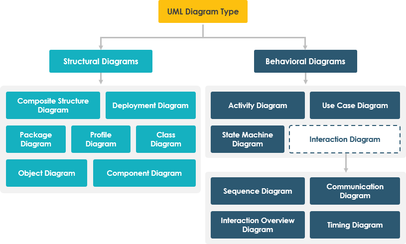 Mastering the 14 UML Diagram Types: A Comprehensive Tutorial for Software Architects
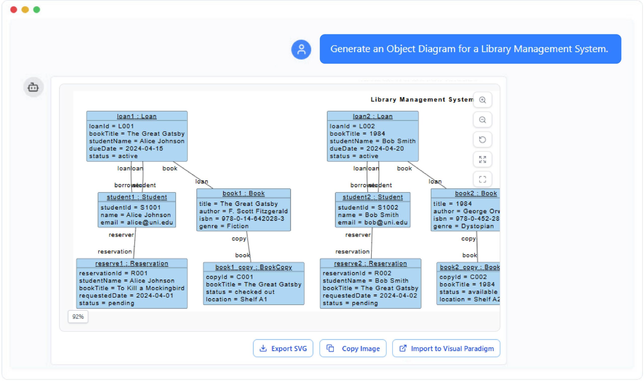 Introduction to Conversational Modeling with VP AI Chatbot
 Mastering the UML Class Box: A Comprehensive Guide to Software Architecture and Modeling
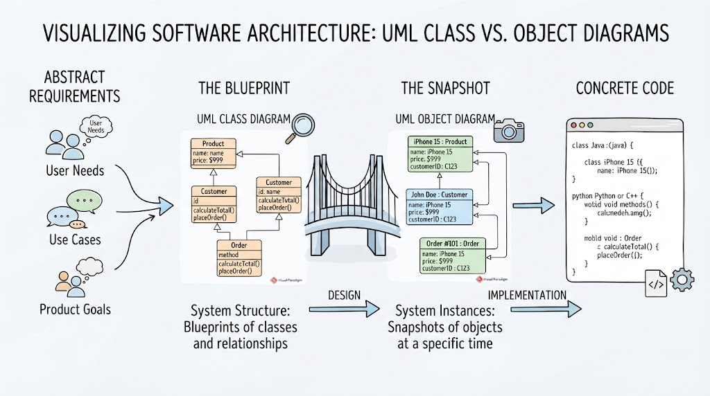 From Abstract Ideas to Concrete Code: Mastering UML Class vs. Object Diagrams