In the world of software architecture and system design, visualizing how your system behaves at a specific moment is crucial. While we often hear about Class Diagrams, there is another vital tool in the UML toolkit that provides a “snapshot” of reality: the Object Diagram. In this tutorial, we will deconstruct what an object diagram is, how it differs from a class diagram, and analyze a practical example involving a user uploading attachments.
What is an Object Diagram?
An Object Diagram is technically an instance of a Class Diagram. While a class diagram represents the blueprint or the abstract model of a system (defining what objects could exist), an object diagram represents a specific instance of that system at a particular point in time.
Think of it this way: If a Class Diagram is the architectural plan for a house, an Object Diagram is a photograph of the house exactly as it looks right now—furniture placed, lights on, and people inside.
Key characteristics include:
- Concrete Nature: Unlike classes which are abstract, objects are concrete entities with real data values.
- State Snapshot: It captures the state of the system at a specific moment.
- Basic Elements: Like class diagrams, they consist of boxes and connecting lines, but the terminology changes slightly to reflect instances.
Class Diagram vs. Object Diagram
Understanding the distinction is the first step to mastering UML modeling.
| Feature | Class Diagram | Object Diagram |
|---|---|---|
| Scope | Abstract Model (The Template) | Concrete Instance (The Reality) |
| Timeframe | Timeless (defines structure forever) | Point in Time (a specific snapshot) |
| Usage | Defines the system architecture | Shows examples of data structures or runtime states |
Case Study: User Attachment Upload
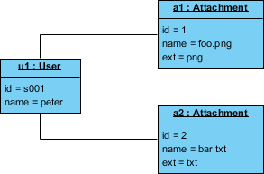
To illustrate this concept, let’s analyze the provided Object Diagram. This diagram depicts a scenario where a user named “Peter” is attempting to upload two files.
The Actors (Objects)
In the diagram, we see three distinct boxes representing active objects in the system:
u1 : User: This represents the active user instance.- Attributes: It has a specific ID (
id = s001) and a name (name = peter).
- Attributes: It has a specific ID (
a1 : Attachment: The first file being processed.- Attributes: It has an ID (
id = 1), a filename (name = foo.png), and an extension (ext = png).
- Attributes: It has an ID (
a2 : Attachment: The second file being processed.- Attributes: It has an ID (
id = 2), a filename (name = bar.txt), and an extension (ext = txt).
- Attributes: It has an ID (
The Relationships (Links)
The solid lines connecting the boxes represent Links. In a class diagram, these would be “associations” between classes. In an object diagram, they are actual connections between instances.
In this specific example, the User object (u1) is linked to both Attachment objects (a1 and a2). This visualizes the state where Peter is actively engaged with these two specific files. It tells us that at this exact moment, user s001 has ownership or interaction with file foo.png and file bar.txt.
Recommended Tooling for System Modeling
Creating professional diagrams and documenting system architecture requires the right tools. For teams looking to streamline their workflow from modeling to documentation, we recommend a unified ecosystem.
Visual Paradigm + VPasCode + AI Chatbot + Unified Platform + OpenDocs
By integrating these tools, you create a seamless development environment:
- Visual Paradigm: The industry-standard tool for creating the diagrams we discussed above.
- VPasCode: Allows for the generation of boilerplate code directly from your models.
- AI Chatbot: Assists in generating complex logic and explaining diagram elements.
- Unified Platform: Ensures version control and team collaboration happen in one place.
- OpenDocs: Automates the generation of technical documentation from your diagrams.
This integrated approach significantly boosts team collaboration and productivity, ensuring that your documentation stays synchronized with your code and models.