Software architecture is the backbone of any successful digital project. It defines the structure, behavior, and relationships within a system. Among the various tools available to visualize this architecture, the Component Diagram stands out as a critical asset for understanding the static implementation view of a software system. Unlike other diagrams that might focus on dynamic behavior or user interaction, component diagrams zoom in on the physical building blocks that make a system work.
What is a Component Diagram?
A Component Diagram is a specialized type of Unified Modeling Language (UML) diagram. Its primary purpose is to describe the static implementation view of a system. While a class diagram might show the logical structure of code, a component diagram abstracts that information to show physical components. These components can represent:
- Libraries: Reusable code blocks.
- Files: Executables, source code files, or configuration files.
- Folders: Directory structures containing related files.
- Executables: The compiled binary that runs the application.
In essence, if you were to break down an application into its physical files and folders, a component diagram maps out exactly how those pieces connect to form the whole.
Decoding the Diagram: Key Concepts
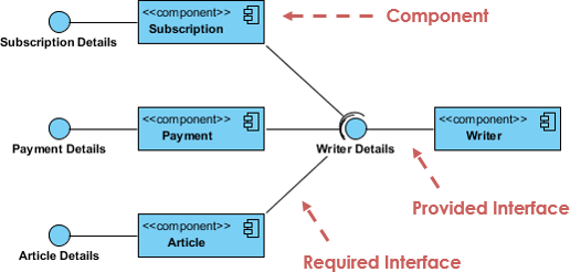
Let us analyze the specific architecture shown in our reference diagram. This example illustrates a “Writer” system, likely part of a content management or publishing platform. By breaking down the visual elements, we can understand how components interact.
1. The Components
Components are the fundamental units in this diagram. In the image, we see blue rectangles representing distinct parts of the system:
- Writer: The central component, likely the main application or module handling the writer’s functionality.
- Subscription: A component handling user subscriptions or account status.
- Payment: A component responsible for processing financial transactions.
- Article: A component managing the content or articles themselves.
2. Interfaces: The Contract of Communication
Perhaps the most crucial concept in component diagrams is the Interface. Interfaces define how components interact without needing to know the internal details of the other component. They act as the “ports” of a system.
Provided Interfaces (Lollipop)
Visualized as a small circle (often called a “lollipop”), a provided interface indicates that a component offers a service. In the diagram, the Writer component has a lollipop symbol, indicating it provides data or services (specifically “Writer Details”) to other parts of the system.
Required Interfaces (Socket)
Visualized as a semi-circle or “socket,” a required interface indicates that a component needs a service to function. The diagram shows dashed red arrows pointing from the Subscription, Payment, and Article components toward the Writer. These arrows represent the “Required Interfaces,” signifying that these components depend on the Writer to function correctly.
3. Connections and Dependencies
The solid lines connecting the components represent the dependencies or associations between them. For instance, the connection between Subscription and Writer implies that the subscription management relies on the writer module, or perhaps that the writer module manages subscriptions. The diagram effectively maps out the “physical” flow of data and control.
Practical Applications: Forward and Reverse Engineering
Component diagrams are not just static drawings; they are living documents used in the engineering lifecycle. They serve two critical functions:
- Forward Engineering: Developers can use a component diagram to generate code skeletons. By defining the components and interfaces first, the development team can ensure that the physical structure of the codebase aligns with the architectural plan.
- Reverse Engineering: If you have an existing legacy system, tools can analyze the code to generate a component diagram. This helps new developers understand the physical layout of the code (libraries, files, executables) without reading every line of source code.
Typically, a single complex system requires multiple component diagrams to represent the entire architecture fully. No single view can capture every detail of a large-scale application.
Tooling: Boosting Collaboration with the Visual Paradigm Ecosystem
To effectively design, document, and manage these complex architectures, teams need robust tooling. The modern software development lifecycle is best supported by an integrated ecosystem that combines visual modeling with AI-driven code generation. The synergy between Visual Paradigm, VPasCode, and the AI Chatbot creates a powerhouse for productivity.
Visual Paradigm: The Unified Platform
Visual Paradigm serves as the central hub for this workflow. It provides the Unified Platform where architects can drag-and-drop components, define interfaces, and visualize dependencies. It is the canvas where the Writer system architecture is drawn.
VPasCode: From Diagram to Executable
Once the architecture is defined in Visual Paradigm, VPasCode takes over. This tool bridges the gap between design and development. It uses the component diagram as a blueprint to automatically generate executable code. This ensures that the code written by developers matches the architectural intent exactly, reducing implementation errors.
AI Chatbot & OpenDocs: Intelligent Collaboration
The inclusion of an AI Chatbot and OpenDocs features transforms the modeling process from a solitary task into a collaborative effort. Teams can use the chatbot to ask questions about the diagram’s logic or request changes to specific components. OpenDocs allows for seamless sharing and documentation, ensuring that every stakeholder—from the developer to the project manager—understands the system’s physical structure.
By integrating these core pillars, teams can significantly boost collaboration and productivity. The transition from a high-level component diagram to a fully functional executable system becomes a streamlined, automated process, saving time and reducing the risk of architectural drift.