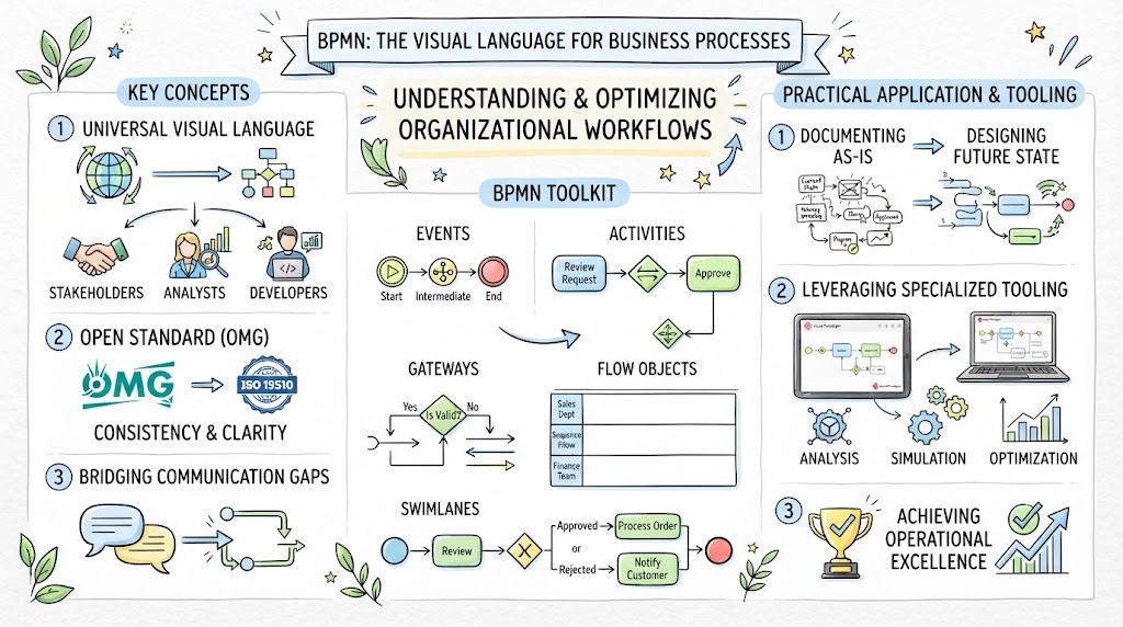
In the world of Business Process Management (BPM), clarity is king. A process model that is ambiguous is a process that cannot be automated or optimized. At the heart of the Business Process Model and Notation (BPMN) standard lies the fundamental building block: the Event.
Events are the “heartbeat” of a process. They mark the beginning, the middle, and the end of workflow activities. While they may look like simple circles on a diagram, the geometry and the markers within them tell a complex story about timing, triggers, and system states. This tutorial breaks down the anatomy of BPMN events, distinguishing between Start, Intermediate, and End events, and explains how to model them effectively using tools like Visual Paradigm.
1. The Anatomy of an Event: Geometry as Meaning
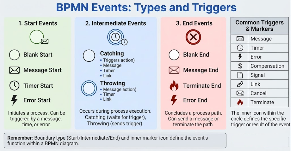
Before diving into specific types, one must understand the visual language of BPMN. All events share a common geometric shape: the Circle. However, the nuance lies in the boundary (stroke) thickness of that circle. This visual distinction is the first clue a stakeholder needs to understand the lifecycle of a process.
- Thin/Single Outline: Indicates a Start Event. It represents a clean initiation.
- Double Outline: Indicates an Intermediate Event. It represents a state of waiting or an interruption within the flow.
- Thick/Bold Outline: Indicates an End Event. It represents a termination or completion.
Understanding the Inner Marker
While the outline determines the event’s position in the lifecycle, the inner marker icon defines the specific trigger or result. A circle with a thick outline is a generic “End,” but a circle with a thick outline and a lightning bolt inside is specifically an “Error End.” This allows for granular control over process logic.
2. Start Events: The Trigger
Every process must begin somewhere. Start events are the catalyst that sets the workflow in motion. They are the entry points into your diagram and generally do not have incoming sequence flows (meaning nothing precedes them in the diagram).
Common Types of Start Events
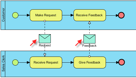
- Message Start Event: This is the most common trigger in business environments. It represents the receipt of external information, such as an email order, a form submission, or a physical package arriving at a warehouse.
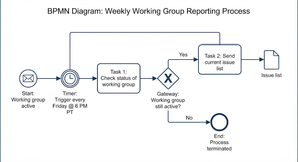
- Timer Start Event: This represents a scheduled trigger. It is used for recurring tasks, such as a “Monthly Report Generation” or a “Payroll Run” that happens at a specific time.
- Signal Start Event: Used for global triggers where a signal is broadcasted to multiple processes simultaneously.
Modeling Tip
When modeling a Start Event, ensure you define the specific trigger. Don’t just draw a circle; add an envelope icon to represent a message or a clock to represent a timer. This clarity is essential for automation rules.
3. Intermediate Events: The Interruption or Wait
Once a process has started, it rarely runs in a straight line to completion without interruption. Intermediate events occur in the middle of the process. They are defined by their double-line border and act as the “glue” or the “stop signs” of a workflow.
Catching vs. Throwing
Intermediate events are categorized by their behavior relative to the flow:
- Catching Events: These events pause the process to wait for something. For example, a process might flow into a “Wait for Customer Response” event. The process cannot proceed until the customer replies.
- Throwing Events: These events actively trigger an action that sends something out. For instance, a process might flow into a “Send Notification” event, which then triggers an external email.
Boundary Events: The Exception Handler
A unique feature of Intermediate Events is the Boundary Event. These are attached directly to the edge of a Task (or Activity). They model exceptions or parallel behaviors.
Example: Imagine a task for “Process Application.” If this task takes too long, you might attach a “Timer Boundary Event” that says “If not completed within 3 days, escalate to Manager.” This allows the process to branch off into an error-handling path without stopping the main flow immediately.
4. End Events: The Result
The End Event signifies the completion of a process path. Visually, it is the most distinct event type due to its bold, thick border. Unlike Start events, End events do not have outgoing flows; they are the terminus of the logic.
Multiple End Points for Different Outcomes
A common misconception is that a process has only one end. In reality, complex processes often have multiple End Events to represent different outcomes:
- Success End: A “Blank End” or one with a checkmark, indicating a “Happy Path” where the task was completed successfully (e.g., “Order Fulfilled”).
- Error End: A “Terminate End” or one with a lightning bolt, indicating that the process failed or an exception was fatal (e.g., “Payment Declined”).
5. Practical Application: Modeling in Visual Paradigm
Theoretical knowledge is vital, but practical application is where mastery is achieved. Visual Paradigm offers a robust, drag-and-drop interface designed to adhere strictly to BPMN 2.0 standards. Here is a step-by-step guide to implementing these concepts.
Step 1: Setting the Stage
Open Visual Paradigm and create a new BPMN Diagram. Locate the Shape Repository (typically found in the sidebar). Expand the Events category. You will see the distinct icons for Start, Intermediate, and End events ready for use.
Step 2: Creating the Trigger (Start Event)
Drag a Start Event onto your canvas. To customize the trigger, right-click the shape and select Open Specification. You can change the internal icon to a “Clock” for a Timer Start or an “Envelope” for a Message Start. Use the “Resource Catalog” (the small arrow appearing on hover) to quickly drag a Sequence Flow to the first task.
Step 3: Managing Flow (Intermediate Events)
To model a “Wait for Approval,” drag an Intermediate Catch Event onto a sequence line. Visual Paradigm will automatically break the line and insert the event, maintaining the flow logic.
For exception handling, drag a Timer Boundary Event directly onto the edge of an existing Task shape. The software will snap it to the border, visually indicating that this event interrupts or runs parallel to the task if the timer expires.
Step 4: Defining Outcomes (End Events)
Finally, drag an End Event to the termination point of your flow. If your process has distinct outcomes, use multiple End Events. Change the icon inside one to a “Checkmark” (Terminate/Success) and the other to a “Lightning Bolt” (Error). This visual distinction helps stakeholders immediately understand the possible results of the process.
Conclusion
By understanding the anatomy of BPMN events—the thin, double, and thick circles—you unlock the ability to design processes that are not just diagrams, but executable logic. Whether you are initiating a workflow, managing a delay, or terminating a failed transaction, the correct use of events ensures your business processes are clear, efficient, and robust.