Business Process Model and Notation (BPMN) is the industry standard for visualizing business processes. It acts as a universal language between business stakeholders and technical developers, bridging the gap between abstract workflows and executable systems. In this tutorial, we will deconstruct a real-world loan request process diagram to understand the architecture of process modeling, how to interpret swimlanes, and how to design logical decision flows.
1. The Foundation: Swimlanes and Responsibility
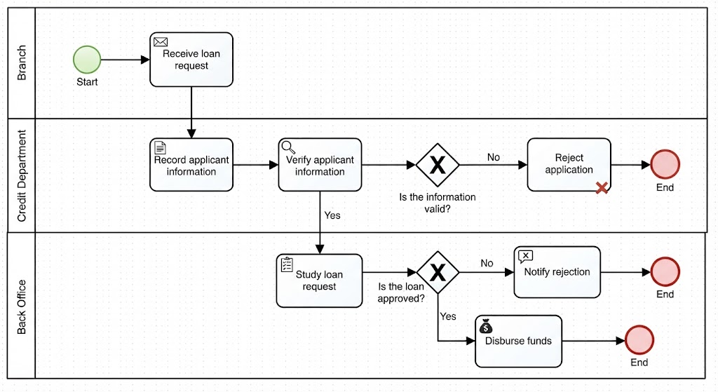
Before diving into the flow of data, it is crucial to understand who is doing what. In BPMN, this is achieved through “Swimlanes” (or Pools). The provided diagram utilizes a multi-lane architecture to segregate responsibilities across different organizational departments.
- The Branch: This is the entry point. The “Branch” lane typically represents the front-line staff or the customer interface. Their responsibility here is the initial intake of the application.
- The Credit Department: This lane houses the risk assessment team. They are responsible for validating the data and making the initial eligibility judgment.
- The Back Office: This represents the operational execution. They handle the final study of the loan, the notification of results, and the financial disbursement.
Key Takeaway: In process modeling, complexity is often managed by separating “Who” (Swimlanes) from “What” (Tasks). If a process spans multiple departments, swimlanes are mandatory.
2. The Sequence: Events and Tasks
The process flow is driven by specific symbols. Understanding the distinction between an Event (the trigger or result) and a Task (the work being done) is fundamental.
Start and End Events
Every process needs a trigger and a conclusion.
- Start Event: Represented by a green circle, the process begins when the “Receive loan request” task is triggered. This is the entry point.
- End Events: Represented by red circles, these signify the termination of a path. Notice that this process has three distinct end points: rejection after verification, rejection after study, and successful disbursement.
Tasks (Activities)
Tasks are the actual work performed. In this diagram, we see a logical progression:
- Receive loan request: The customer interaction.
- Record applicant information: Data entry.
- Verify applicant information: Validation work.
- Study loan request: Analysis work.
- Disburse funds: The financial transaction.
3. Logic and Control: Exclusive Gateways
The heart of a BPMN diagram is its logic. The diagram uses Exclusive Gateways (represented by diamonds with an ‘X’) to handle decision points. These gateways ensure that the flow follows only one path based on a specific condition.
The Verification Gateway
After the Credit Department verifies information, the process hits a decision point: “Is the information valid?”
- The “No” Path: If the data is invalid, the flow moves to “Reject application.” This is a quick termination loop.
- The “Yes” Path: If valid, the process continues down to the Back Office.
The Approval Gateway
The Back Office then studies the request and faces a second decision: “Is the loan approved?”
- The “No” Path: Leads to “Notify rejection” followed by an End event.
- The “Yes” Path: Leads to “Disburse funds,” the primary success outcome.
4. Best Practices for Beginners
When modeling your own processes, keep these architectural principles in mind to ensure your diagrams are readable and maintainable:
- Keep it Simple: Don’t try to model every exception immediately. Start with the “Happy Path” (the ideal scenario where everything goes right).
- Clear Naming: Use action-oriented verbs for tasks (e.g., “Verify” rather than “Verification”).
- Label Your Paths: Never leave a gateway without a clear label (e.g., Yes/No, Valid/Invalid).
- Ensure Reachability: Ensure that every path in your diagram eventually leads to an End Event. Dead-ends create confusion.
5. Recommended Tooling for Modeling
To effectively create and maintain diagrams like the one analyzed above, using professional modeling software is essential. It ensures that you adhere to BPMN 2.0 standards and allows for features like auto-layout and validation.
For this tutorial, we highly recommend the Visual Paradigm BPMN Tool. It offers a comprehensive suite of features specifically designed for business analysts and developers, including:
- Drag-and-Drop Interface: Easy-to-use symbols for Events, Tasks, and Gateways.
- Collaboration Features: Allows teams to work on the same process model simultaneously.
- Code Generation: Can generate BPMN XML files for integration with workflow engines.
- Validation: Built-in checks to ensure your diagrams are valid and error-free.
By mastering the concepts of Swimlanes, Events, and Gateways, you can transform complex business requirements into clear, actionable visual diagrams.