In the realm of business process management, clarity is currency. Whether you are a systems analyst, a software developer, or a business operations manager, the ability to visualize complex workflows is essential. This tutorial breaks down the Inventory Availability Process shown in the diagram above, teaching you how to model decision logic using Business Process Model and Notation (BPMN) standards.
Understanding the Architecture
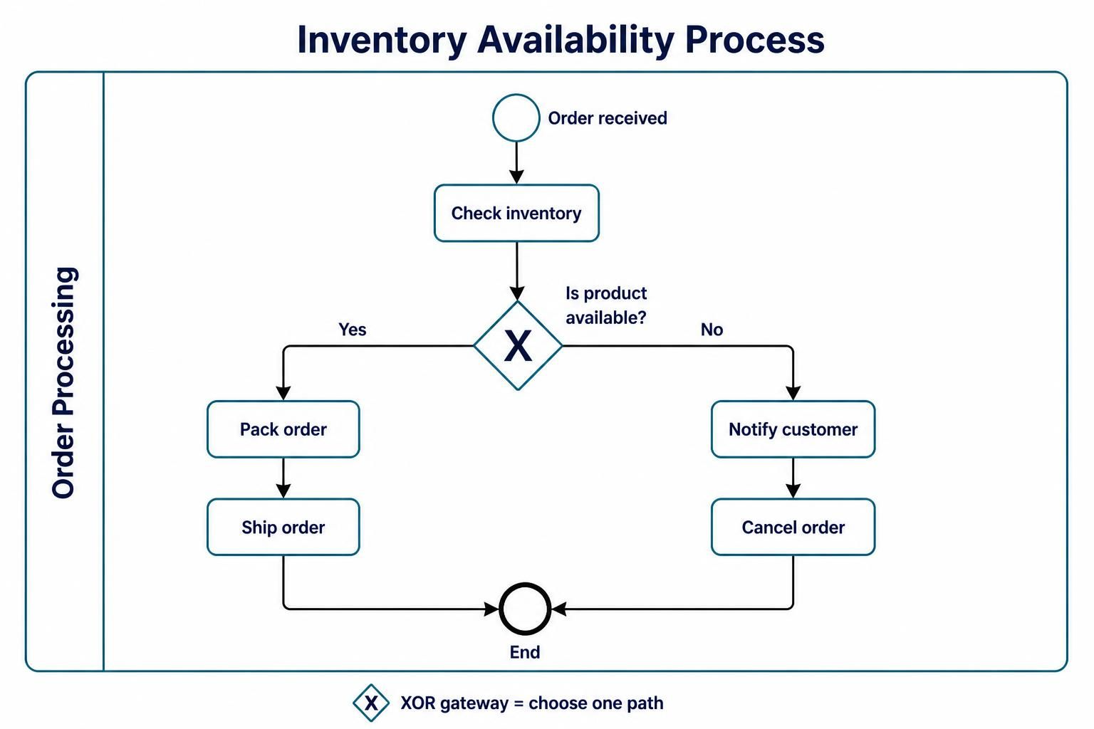
The diagram illustrates a classic “Order Processing” lifecycle. It is not just a list of tasks; it is a logical structure that dictates how a business reacts to external events. The process begins with a trigger and branches based on data conditions.
The architecture follows a linear flow interrupted by a critical decision point. This structure ensures that resources (like inventory) are checked before commitments (like shipping) are made, preventing fulfillment errors.
Decoding the BPMN Elements
To understand this model, we must break down the specific symbols used. BPMN is a standardized language, and every shape serves a distinct purpose.
1. Start Event: The Trigger
The circle at the top labeled “Order received” is the Start Event. In BPMN, this represents the moment the process is initiated. It is a passive state waiting for an external input (the order) to begin the active workflow.
2. Activities: The Work
The rounded rectangles, such as “Check inventory” and “Pack order”, represent Tasks or Activities. These are the specific actions performed by a human or an automated system. Notice the flow of data: the system cannot proceed to the next step until the current activity is completed.
3. The XOR Gateway: Decision Logic
The diamond shape containing an X is the most critical element in this diagram. It is known as an XOR Gateway (Exclusive OR).
- Function: It evaluates a condition. In this case: “Is product available?”
- Behavior: The “X” signifies that only one path can be taken. It is impossible to go both the “Yes” and “No” paths simultaneously. The process splits here, forcing a binary choice.
4. End Event: The Conclusion
The thick-bordered circle at the bottom labeled “End” is the End Event. Regardless of whether the product was available or not, the process must eventually converge here to signify that the transaction has been formally closed.
Step-by-Step Logic Walkthrough
Let us trace the execution flow of this process model to understand the logic.
- Inception: The system detects an incoming order. The Start Event fires.
- Verification: The process moves to the Check inventory activity. The system queries the database for stock levels.
- Decision Point: The flow hits the XOR Gateway.
- Path A (Yes): If stock > 0, the flow moves to “Pack order” and “Ship order”.
- Path B (No): If stock = 0, the flow diverts to “Notify customer” and “Cancel order”.
- Termination: Both paths merge at the End Event, finalizing the process instance.
Implementation with Recommended Tooling
While understanding the theory is vital, implementing these models requires the right tools. For professional-grade BPMN modeling that supports both visual drag-and-drop and code-based generation, the industry recommends using Visual Paradigm BPMN.
Visual Paradigm offers a robust environment for creating these diagrams. However, for developers who prefer an automated approach or need to integrate modeling into a CI/CD pipeline, Visual Paradigm BPMN and AI capabilities are game-changers. By leveraging AI, you can generate complex diagrams from text prompts or code, significantly reducing the time spent on manual drawing and ensuring 100% adherence to BPMN standards.
Modeling the Logic (Code Representation)
To demonstrate how this visual flow translates into machine-readable logic, consider the following pseudo-code representation of the decision structure:
graph TD
    Start((Order Received)) --> CheckInventory[Check Inventory]
    CheckInventory --> Decision{Is product available?}

    Decision -- Yes --> PackOrder[Pack Order]
    PackOrder --> ShipOrder[Ship Order]
    ShipOrder --> End((End))

    Decision -- No --> NotifyCustomer[Notify Customer]
    NotifyCustomer --> CancelOrder[Cancel Order]
    CancelOrder --> End
Conclusion
This tutorial has deconstructed the Inventory Availability Process, demonstrating how BPMN serves as a universal language for defining business logic. By utilizing the XOR gateway, we ensure that our processes are deterministic—handling every scenario explicitly.
For organizations looking to adopt this level of process rigor, it is highly recommended to utilize Visual Paradigm BPMN for its comprehensive feature set. Furthermore, integrating Visual Paradigm BPMN and AI allows teams to future-proof their modeling efforts, enabling rapid prototyping and automated documentation that keeps pace with modern development cycles.