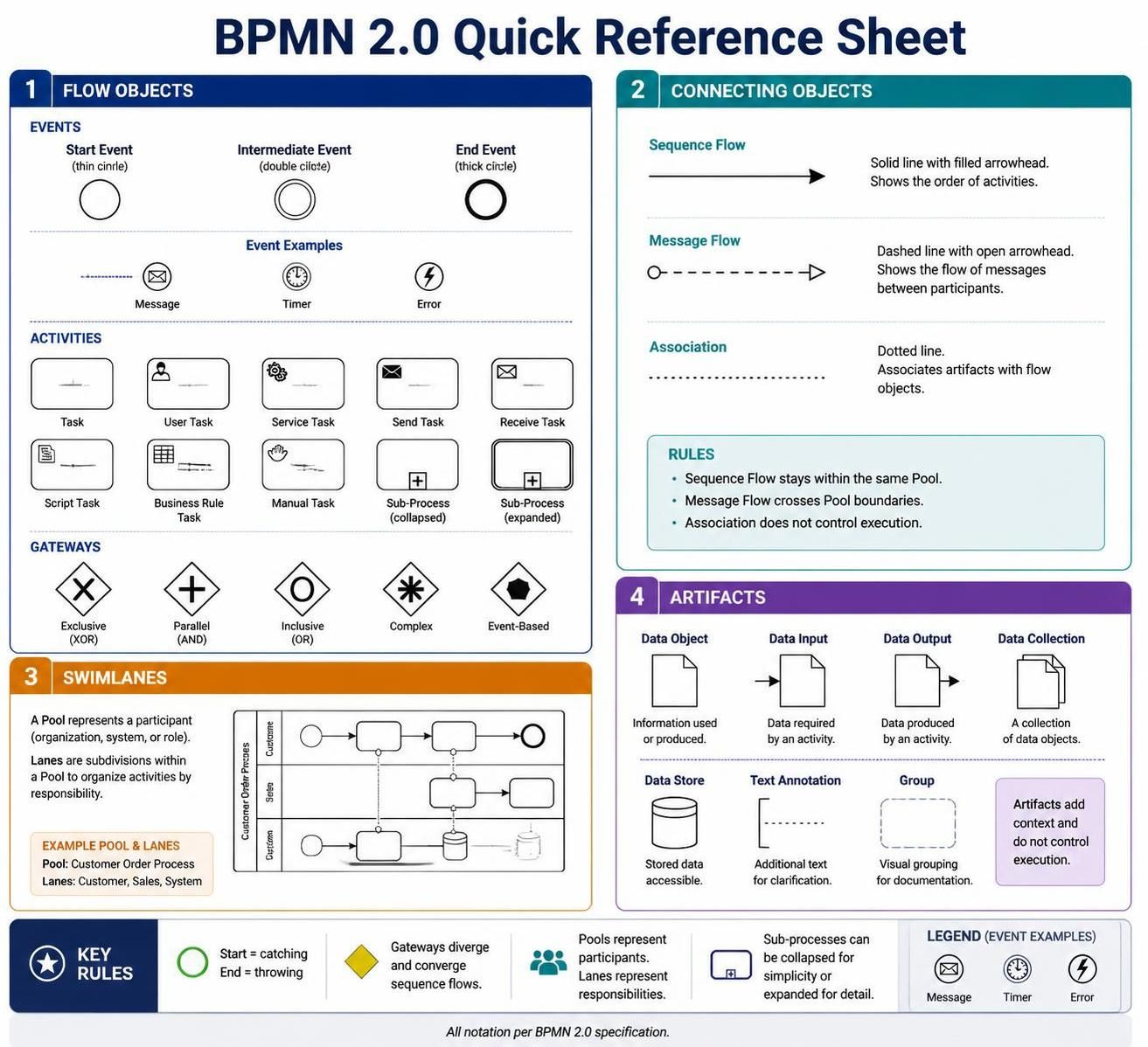
Welcome to the definitive guide on Business Process Model and Notation (BPMN) 2.0. As a technical tutor, I view BPMN not just as a drawing tool, but as a standardized engineering language for describing complex business workflows. Whether you are designing a customer onboarding flow or automating a backend data pipeline, understanding the core architecture of BPMN is essential.
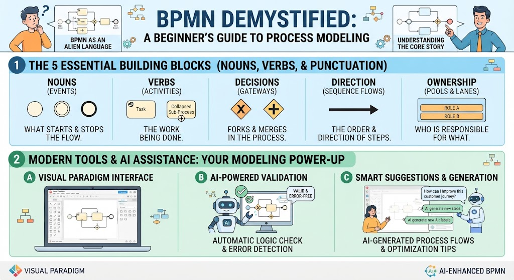
This tutorial breaks down the system into its four fundamental building blocks: Flow Objects, Connecting Objects, Swimlanes, and Artifacts. By mastering these elements, you will be able to create models that are not only visually clear but also executable by process engines.
1. The Engine: Flow Objects
Flow Objects are the core graphical elements that define the behavior of a process. They dictate what happens, when it happens, and how the process flows. They are categorized into three distinct types: Events, Activities, and Gateways.
Events: The Triggers and Outcomes
In BPMN, events are depicted as circles and represent something that happens during the course of a process. They are classified by their behavior:
- Start Events (Catching): Every process must begin with a start event. These are represented by a single thin circle. They “catch” a trigger, such as receiving an email or a timer expiring. If you see a circle with an envelope icon, it is a Message Start Event.
- Intermediate Events: These occur between the start and end. Represented by a double-lined circle, they can either catch a signal (waiting for a specific condition) or throw a signal (sending a notification mid-process).
- End Events (Throwing): These mark the conclusion of a process path. Represented by a thick black-bordered circle, they always “throw” an outcome because there is no subsequent process to catch it. Common examples include terminating the process or sending a final confirmation.
Activities: The Work Units
Activities are depicted as rectangles with rounded corners and represent work performed. They are the meat of the process diagram.
- Tasks: The most granular level of work. A User Task is performed by a human (often with software support), while a Service Task is an automated action performed by a system or web service. A Manual Task requires no system support at all.
- Sub-Processes: These are compound activities that contain other flow objects. They allow you to abstract complexity.
- Collapsed: Hidden for simplicity.
- Expanded: Showing internal details.
- Transaction: A specialized sub-process where all activities must succeed together or the whole thing is cancelled.
Gateways: The Decision Logic
Gateways control the divergence and convergence of sequence flows. They are depicted as diamonds and determine the path of the process based on logic.
- Exclusive Gateway (XOR): The classic “If/Else” logic. Only one path can be taken based on a condition.
- Parallel Gateway (AND): Splits the flow into multiple concurrent paths or joins them. All paths must complete before the process can proceed.
- Inclusive Gateway (OR): One or more paths can be taken based on conditions. This is often used for complex branching where multiple options are valid simultaneously.
2. The Connectors: Connecting Objects
Connecting objects link flow objects to show the order and relationships. They define the control flow and data flow between the elements.
Sequence Flow
This is the most common connector, depicted as a solid line with a solid arrowhead. It shows the order in which activities are performed. A critical architectural rule is that Sequence Flow cannot cross pool boundaries; it represents the internal logic of a single participant.
Message Flow
When processes interact across different boundaries, we use Message Flow. It is depicted as a dashed line with an open circle at the start and an arrowhead at the end. This represents communication between two separate participants (Pools). It connects objects across pool boundaries but never connects two objects within the same pool.
Association
Associations are dotted lines used to link artifacts (like data or text) to flow objects. Crucially, they do not affect the flow order or execution; they are purely for documentation and context.
3. The Structure: Swimlanes
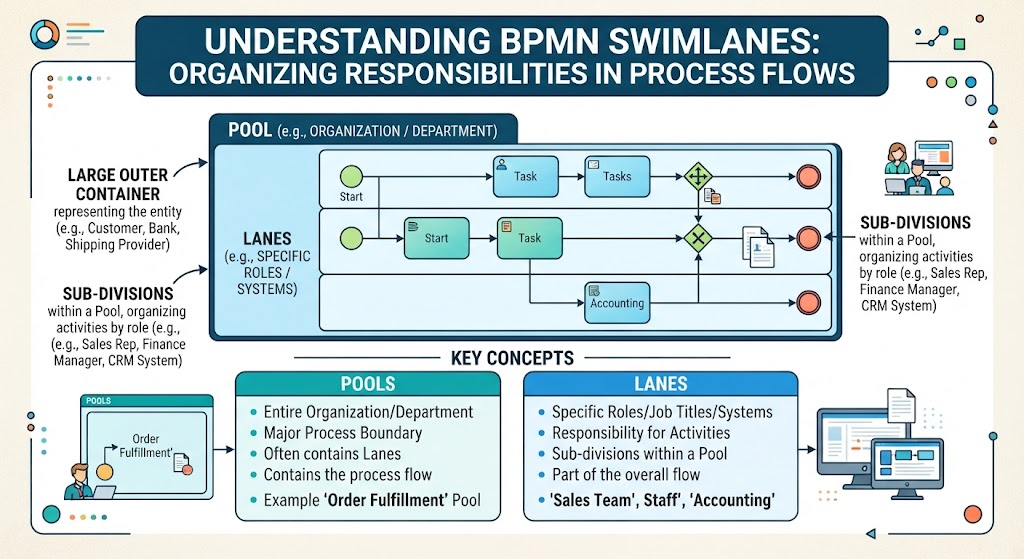
Swimlanes are used to organize activities by responsibility, adding a layer of clarity regarding who is doing what.
- Pool: Represents a major participant in the process, such as a different organization, department, or system. Pools define the boundaries of interaction.
- Lane: Sub-divisions within a Pool. Lanes represent specific roles, individuals, or systems within that participant’s organization. If a process involves a “Customer” and a “Sales Team,” these would typically be distinct lanes within a single Pool.
4. The Context: Artifacts
Artifacts provide additional information about the process but do not affect the flow execution. They are the “metadata” of the diagram.
- Data Objects: Represent data required for or produced by a task. This includes Data Input (required to start), Data Output (generated by), and Data Stores (persistent databases).
- Groups: Visual containers used to logically group activities for readability. Unlike sub-processes, groups have no semantic meaning in execution; they are purely for organizational clarity.
- Annotations: Text notes used to provide additional context or explanation for readers.
Pro Tip for Tooling
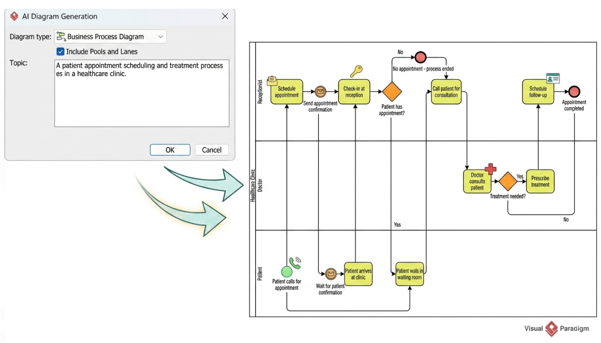
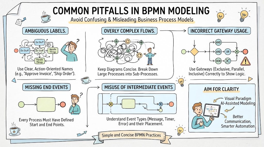
When using tools like Visual Paradigm or similar BPMN engines, remember that the distinction between a Sequence Flow and a Message Flow is often the most common source of modeling errors. A Sequence Flow implies “Next Step,” while a Message Flow implies “Handoff.”
Summary
By combining these four categories, you can construct a robust BPMN diagram. Start with the Flow Objects to define your logic, use Connecting Objects to sequence them, organize them with Swimlanes to assign responsibility, and finally, add Artifacts to clarify the data context. This structured approach ensures your diagrams are not just pictures, but precise technical specifications.