


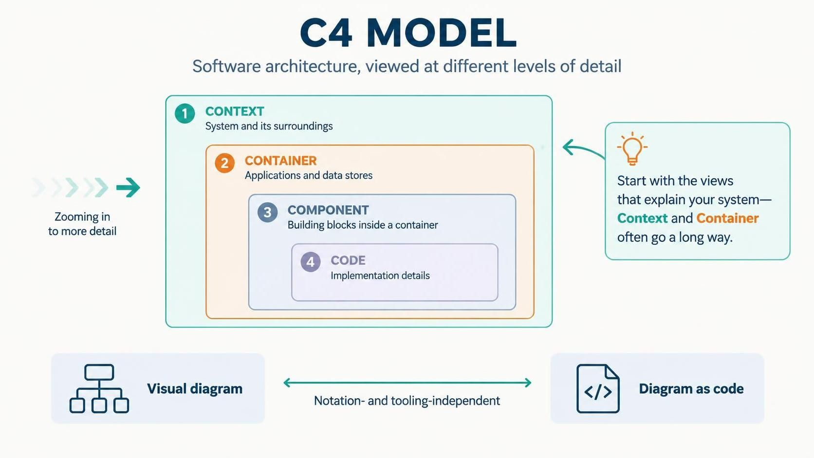
Understanding how software fits together is one of the most critical skills for any architect or developer. The C4 Model provides a structured way to visualize software architecture at different levels of detail. Instead of trying to capture everything in one massive diagram, the C4 Model encourages you to “zoom in” to specific areas of interest.
In this tutorial, we will explore the four core levels of the C4 Model and demonstrate how to leverage the Visual Paradigm (VPasCode) tool to generate these diagrams using text-based descriptions. This approach ensures your documentation is version-controlled, readable, and easy to maintain.
1. The Four Core Levels of Abstraction
The C4 Model is built on the principle of abstraction. You can view your system from a high-level bird’s-eye view or dive deep into the specific implementation details. The model defines four distinct levels:
Level 1: Context Diagram
The Context diagram is the starting point. It shows your system as a single “box” in the center and illustrates how users and other external systems interact with it. It answers the question: “What does this system do, and who uses it?”
- System Box: Represents the software you are building.
- People: Users, administrators, or external actors.
- System of Systems: External applications that communicate with your system (e.g., a Payment Gateway).
Level 2: Container Diagram
Once you understand the context, you “zoom in” to see what your system is made of. A Container represents a distinct, deployable unit of software, such as a web application, a mobile app, or a database. It answers the question: “What are the building blocks inside the system?”
- Web Applications: React apps, Angular apps, or server-side frameworks (Node.js, .NET).
- Mobile Applications: iOS or Android apps.
- Data Stores: SQL databases, NoSQL stores, or file systems.
Level 3: Component Diagram
Inside each container, there are often multiple Components. These are the building blocks within a container, such as a module, a library, or a specific service. This level answers: “How is this container organized?”
Level 4: Code Diagram
The most granular level is the Code diagram, which maps components to classes and interfaces. While powerful, this level is often best generated automatically from code and is less common in high-level architectural discussions.
2. Tooling Independence: Visual vs. Code
One of the most powerful features of the C4 Model is that it is notation-independent. You do not need to be a skilled artist to create professional diagrams. Visual Paradigm supports two primary workflows:
- Visual Diagramming: Drag and drop elements using the graphical editor.
- Diagram as Code: Write text descriptions that are automatically rendered into diagrams.
By using VPasCode (Visual Paradigm as Code), you can write your architecture in a text file. This allows you to use Git for version control, track changes in pull requests, and generate diagrams automatically in your CI/CD pipeline.
3. Practical Example: Building a Context Diagram
Let’s create a simple Level 1 Context Diagram for an “Online Order Processing System.” We will use the VPasCode syntax to define the system, the user, and the external payment provider.
Copy the following code block into your Visual Paradigm VPasCode editor. This syntax defines the system boundaries and the relationships between actors.
system "Online Order System" {
    // Define the main system
    system_person "Customer"
    system "Payment Gateway"

    // Define relationships
    Person(customer) -> System(online_order_system) "Places orders via"
    System(online_order_system) -> System(payment_gateway) "Processes payments via API"
}

// Configure the diagram to show the C4 Context view
view "Context" {
    include *
}
Understanding the Syntax
In the snippet above:
system_persondefines a human actor.systemdefines an external system or application.- The arrow syntax
A -> B "Label"defines the flow of data or interaction between elements.
4. Moving to the Container Level
After defining the context, you can easily “zoom in” to the Container level. Instead of just one box, the system now breaks down into a Web Application, a Mobile App, and a Database.
system "Online Order System" {
    // Containers (Apps and Data Stores)
    container("Web App", "React.js", "Web Application")
    container("Mobile App", "Flutter", "Mobile Application")
    container_db("Order Database", "PostgreSQL", "SQL Database")

    // Define relationships between containers
    container(web_app) -> container(order_database) "Reads/Writes data"
    container(mobile_app) -> container(web_app) "Calls API"
}
Conclusion
The C4 Model is not just about drawing boxes; it is about communication. By using a standardized set of views, you ensure that stakeholders, developers, and architects are all looking at the same map of the system. By combining this methodology with the power of VPasCode, you can keep your architectural documentation living, breathing, and synchronized with your codebase.