


In the modern landscape of software engineering, bridging the gap between abstract system architecture and executable code is paramount. VPasCode (Diagram-as-Code) represents a paradigm shift, allowing developers to define complex system structures using text-driven syntax that is version-controlled just like application code. This tutorial explores the architecture of a Vending Machine system, demonstrating how to model components, interfaces, and multiplicity constraints using the VPasCode language.
Understanding the System Architecture
The Vending Machine system presented here serves as a classic example of a component-based architecture. Unlike a procedural script, this diagram defines structural relationships between various subsystems. The core of the system is the VendingMachine component, which acts as the central container for the machine’s logic and hardware.
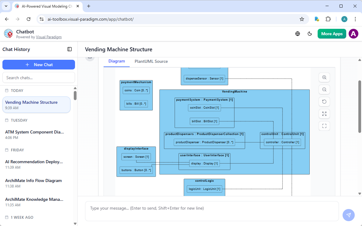
In VPasCode, components are not merely boxes on a canvas; they are typed entities with defined internal states. The diagram reveals a hierarchical structure where the VendingMachine encapsulates several critical sub-systems:
- PaymentSystem: Handles the financial transactions.
- ProductDispensers: Manages the inventory and mechanical release.
- UserInterface: Facilitates interaction with the customer.
- ControlUnit: The central processing logic.
Furthermore, the architecture extends beyond the main container to include external dependencies such as paymentMechanism, displayInterface, controlLogic, and dispenseSensor. These external nodes represent the physical hardware interfaces that the software must communicate with.
Defining the Core Components
The foundation of any VPasCode model is the explicit declaration of the component and its internal properties. In the Vending Machine example, we define the VendingMachine and then detail its internal composition. Notice how the syntax allows us to assign specific types to properties, such as PaymentSystem or ProductDispenserCollection.
// Define the main system container
VendingMachine: Component {
  // Internal financial subsystem
  paymentSystem : PaymentSystem [1]

  // Inventory management subsystem
  productDispensers : ProductDispenserCollection [1]

  // User interaction subsystem
  userInterface : UserInterface [1]

  // Central logic processor
  controlUnit : ControlUnit [1]
}
The notation [1] following a property name indicates cardinality. In this specific architectural model, it asserts that there is exactly one instance of a PaymentSystem within a VendingMachine. This is a crucial detail for code generation, ensuring that the runtime environment instantiates the correct number of objects.
Modeling Multiplicity and Collections
Real-world systems often involve collections of objects rather than single instances. VPasCode handles this elegantly through specific syntax rules for arrays and collections. The diagram highlights two distinct examples of this: the productDispensers and the buttons.
Handling Collections: The Product Dispenser
A vending machine does not have just one product; it has a collection of dispensers. The diagram visualizes this relationship clearly. The productDispensers property is typed as ProductDispenserCollection, which aggregates individual ProductDispenser instances.
productDispensers : ProductDispenserCollection [1] {
  // This defines a collection that can hold zero or more dispensers
  productDispenser : ProductDispenser [0..*]
}
The syntax [0..] is standard UML notation for Zero or Many. This tells the VPasCode engine that a single ProductDispenserCollection can contain an array of ProductDispenser objects. This flexibility is essential for generating scalable code where the number of products can vary.
External Interfaces and Input Mechanisms
While internal components handle logic, the system must interact with the physical world. The displayInterface component in the diagram illustrates how external hardware is modeled. It contains a Screen (exactly one) and a Button collection (zero or many).
// External hardware interaction layer
displayInterface : Component {
  screen : Screen [1]
  buttons : Button [0..*]
}
This separation allows the diagram to distinguish between the logical user interface (part of the VendingMachine) and the physical hardware (the displayInterface). The lines connecting these external nodes back to the main system indicate the data flow or dependency between the software controller and the physical sensor/buttons.
Establishing System Relationships
The power of VPasCode lies in its ability to render these textual definitions into a visual graph. The diagram shows connections between the internal controlUnit and external sensors like dispenseSensor and logicUnit. These relationships are implied by the structural context in VPasCode.
For instance, the dispenseSensor is modeled as a Sensor with cardinality [1]. It is visually connected to the VendingMachine, indicating that the main machine instance relies on this specific sensor to confirm a product has been dispensed. This structural clarity is what makes the diagram “diffable”—if you change the cardinality from [1] to [0..1], the version control system will immediately show a significant architectural change.
Code Generation Potential
By defining these relationships in text, VPasCode enables automatic code scaffolding. The [0..] cardinality on the buttons collection directly translates to a loop or an array initialization in the generated backend code. Similarly, the [1] cardinality on the controller ensures a singleton pattern is implemented.
Conclusion
Modeling the Vending Machine with VPasCode demonstrates the efficiency of text-driven architecture. By defining the VendingMachine as a container with typed properties and explicit cardinalities, developers create a blueprint that is both human-readable and machine-processable. This approach ensures that the visual representation of the system remains in perfect sync with the underlying software requirements.
Related posts:
 Mastering Enterprise Architecture: Building a Unified Ecosystem with Visual Paradigm
 From Prompt to Architecture: Vending Machine Diagrams with VP Unified Platform and AI
 Mastering BPMN: A Step-by-Step Guide to the Order-to-Cash Process Diagram
 Mastering BPMN: A Step-by-Step Guide to the Payment Decision Process