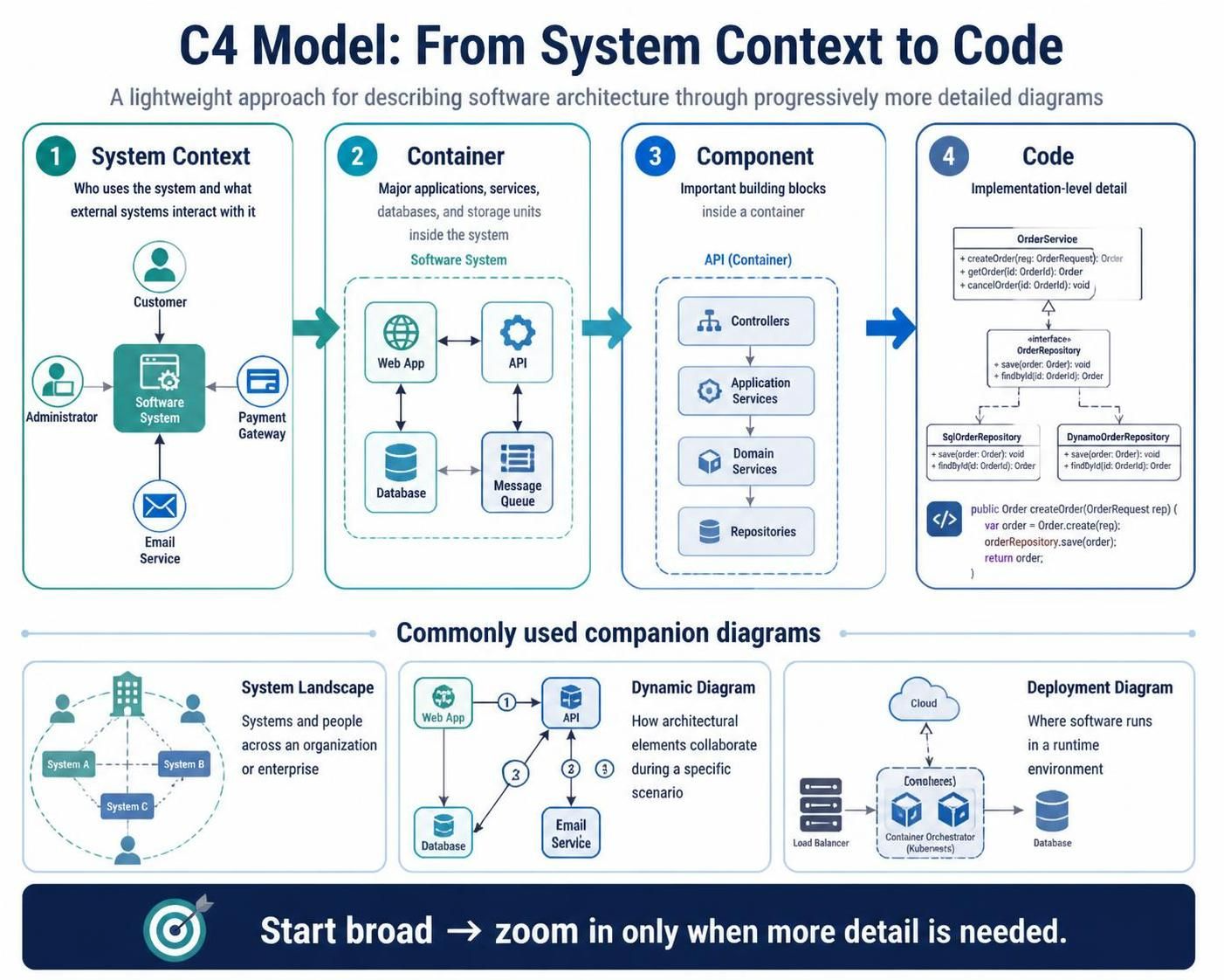
Software architecture is often misunderstood. We tend to get lost in the weeds of code implementation before we understand the high-level goals, or conversely, we define systems so vaguely that developers cannot implement them effectively. The C4 model solves this problem by providing a standardized, hierarchical approach to visualizing software architecture. Instead of a single complex diagram, the C4 model uses a set of four progressively detailed diagram types, allowing you to start broad and zoom in only when necessary.
In this tutorial, we will explore the C4 model layers using an e-commerce order-processing platform as our case study. We will also demonstrate how to leverage VPasCode (Visual Paradigm’s code-to-diagram feature) to generate these diagrams automatically, ensuring your documentation always matches your code.
Understanding the Hierarchy: From Context to Code
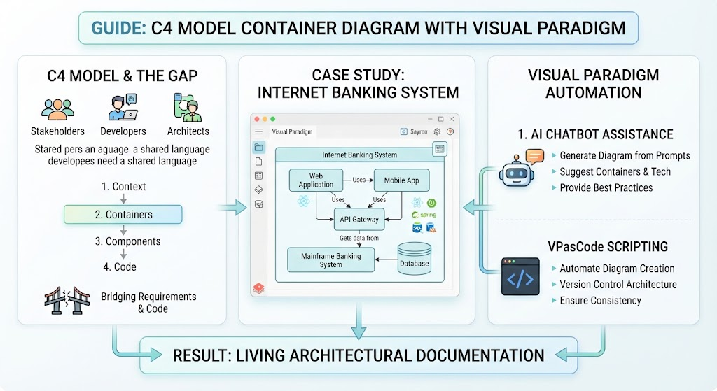
The C4 model is built on the principle that different stakeholders need different views of the system. The model consists of four primary levels:
- System Context: The “helicopter view.” It answers the question: “What is this system, and who uses it?”
- Container: The “high-level technical view.” It answers: “How is the system built, and what are the major technical building blocks?”
- Component: The “implementation view.” It answers: “What are the key parts inside a container that provide functionality?”
- Code: The “detail view.” It answers: “How do these components interact at the class or method level?”
Let’s walk through building these diagrams for our e-commerce platform.
Level 1: The System Context Diagram
The System Context diagram is the most important diagram in the C4 model. It defines the boundaries of your system and identifies the users (people or software) interacting with it. For our e-commerce platform, we need to identify who is placing orders and which external systems handle the money.
When modeling this, you define the Software System (the central box) and the People (Users, Admins) and External Systems (Payment Gateway, Email Service).
@startuml
title E-Commerce System Context Diagram

skinparam componentStyle rectangle
skinparam packageStyle rectangle
skinparam backgroundColor #f9f9f9

actor "Customer" as Customer
actor "Administrator" as Admin
system "E-Commerce Platform" as Platform

package "External Systems" {
    system "Payment Gateway" as Payment
    system "Email Service" as Email
}

Platform --> Customer : Processes orders
Platform --> Admin : Manages inventory
Platform --> Payment : Handles payments
Platform --> Email : Sends notifications
@enduml
Level 2: The Container Diagram
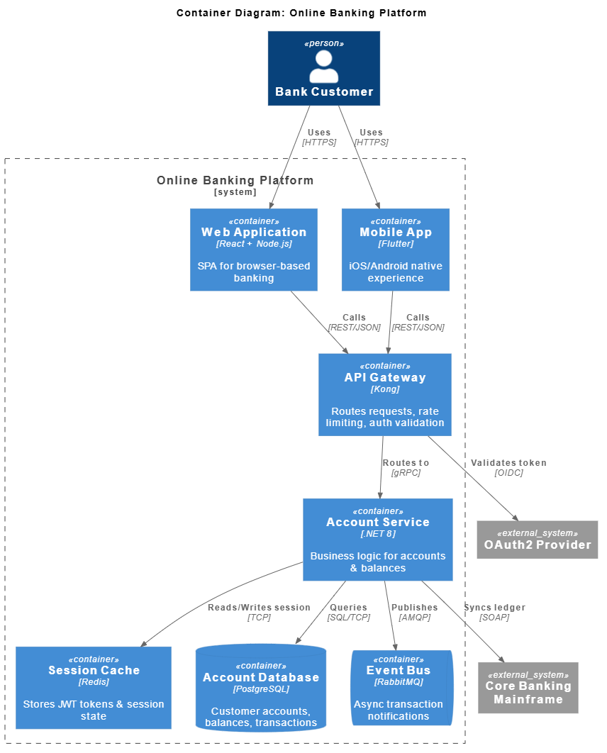
Once the context is clear, we zoom in. A Container is a high-level building block of a system, such as a web application, a mobile application, a microservice, or a database. It represents a deployable unit.
In our e-commerce example, the “E-Commerce Platform” splits into several containers: a Web App for the storefront, an API container for backend services, a Database for storage, and a Message Queue for handling asynchronous tasks like order confirmations.
@startuml
title E-Commerce Container Diagram

skinparam componentStyle rectangle
skinparam packageStyle rectangle

package "E-Commerce Platform" {
    component "Web App (React)" as WebApp
    component "API Service (Node.js)" as API
    database "Order Database (PostgreSQL)" as DB
    component "Message Queue (RabbitMQ)" as MQ
}

WebApp --> API : HTTP REST
API --> DB : SQL
API --> MQ : Publish/Subscribe
@enduml
Level 3: The Component Diagram
Containers are still too high-level for developers who need to understand how the code is structured. The Component diagram zooms in on a specific container (usually the API) to show the internal components. These are cohesive groups of code that perform a specific function.
For the API container, we might see components like Controllers, Application Services, Domain Services, and Repositories. This structure typically follows Clean Architecture or Hexagonal Architecture principles.
@startuml
title API Component Diagram

skinparam componentStyle rectangle
skinparam packageStyle rectangle

package "API Service" {
    component "Controllers" as Controllers
    component "Application Services" as AppServices
    component "Domain Services" as DomainServices
    component "Repositories" as Repositories
}

Controllers --> AppServices : Call methods
AppServices --> DomainServices : Business logic
DomainServices --> Repositories : Data access
@enduml
Level 4: The Code Diagram
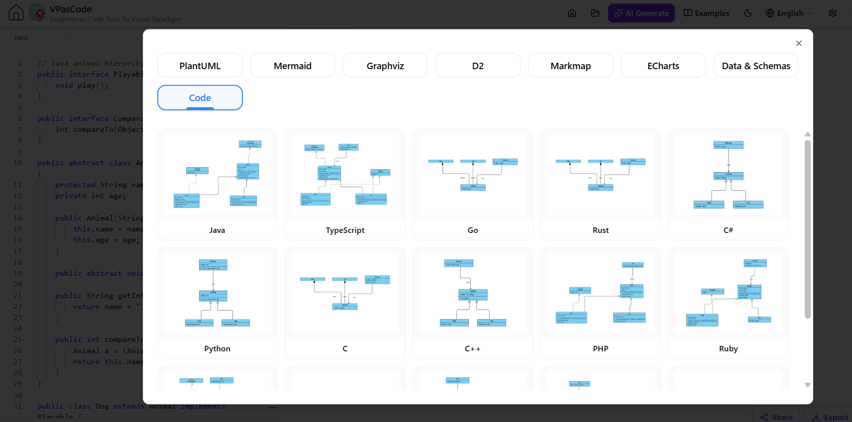
The final level is the Code diagram. While C4 traditionally stops at the Component level for documentation, VPasCode allows you to generate a Code diagram directly from your source code. This shows the actual classes, interfaces, and methods involved in a specific flow.
For example, if we look at the createOrder method, we can see it instantiates an Order object, calls the save method on a repository, and returns the result.
@startuml
title Code Diagram for Order Creation

class OrderService {
    +createOrder(req: OrderRequest): Order
    +getOrder(id: OrderId): Order
    +cancelOrder(id: OrderId): void
}

interface OrderRepository {
    +save(order: Order): void
    +findById(id: OrderId): Order
}

class SqlOrderRepository {
    +save(order: Order): void
    +findById(id: OrderId): Order
}

class DynamoOrderRepository {
    +save(order: Order): void
    +findById(id: OrderId): Order
}

OrderService --> OrderRepository : implements
SqlOrderRepository ..|> OrderRepository : implements
DynamoOrderRepository ..|> OrderRepository : implements

package "Implementation" {
    class Order {
        +id: OrderId
        +items: List[Item]
        +status: OrderStatus
    }
}

OrderService ..> Order : creates
@enduml
Companion Diagrams: Going Beyond the Hierarchy
While the four levels above form the core of C4, real-world systems require additional context. VPasCode supports several companion diagrams that complement the hierarchy:
- System Landscape: Shows how your system fits into the broader enterprise, connecting to other systems across different organizations.
- Dynamic Diagram: Focuses on the flow of messages between containers or components during a specific scenario (e.g., the sequence of an order placement).
- Deployment Diagram: Maps your software containers to physical hardware, showing where the application runs (e.g., Cloud, Kubernetes clusters, Load Balancers).
Why Use VPasCode for C4?
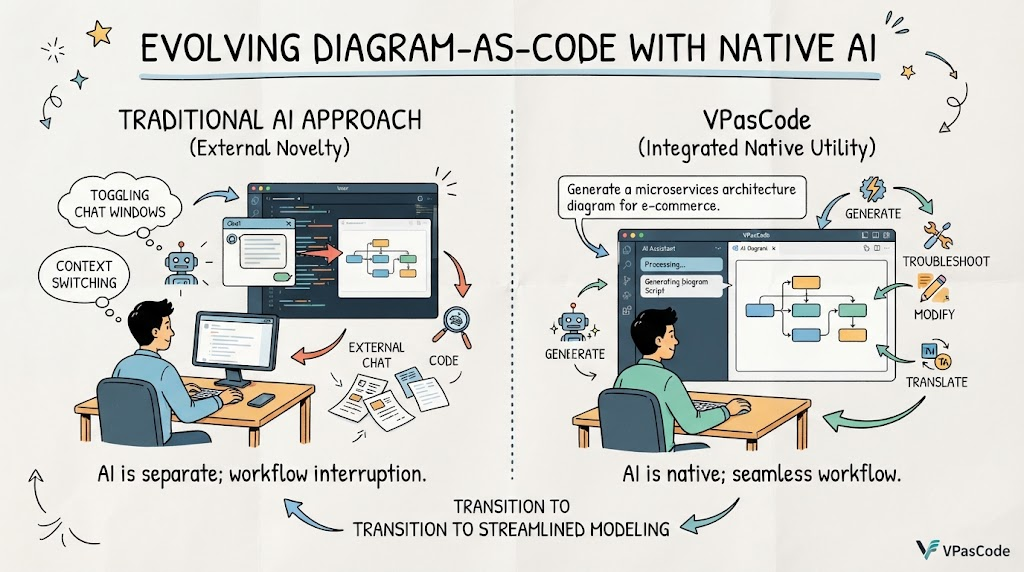
One of the biggest challenges in software architecture is keeping diagrams up-to-date. Developers rarely update diagrams manually because it takes time. VPasCode bridges this gap by allowing you to write code to define your architecture, or even generate diagrams directly from existing codebases.
By using VPasCode, you can:
- Automate Maintenance: If you change a class name in your code, you can regenerate the diagram instantly.
- Enforce Standards: Use templates to ensure all your diagrams follow the C4 standard.
- Integrate into CI/CD: Generate architecture reports as part of your build pipeline to ensure documentation quality.
By mastering the C4 model and leveraging tools like VPasCode, you can create living documentation that serves as a blueprint for your team, ensuring everyone from stakeholders to developers is on the same page.