In the world of software architecture, clarity is king. Before writing a single line of code, developers and architects rely on Unified Modeling Language (UML) to visualize system structures. Two of the most fundamental UML diagrams are the Class Diagram and the Object Diagram. While often confused, they serve distinct purposes: one defines the rules, and the other captures a moment in time.
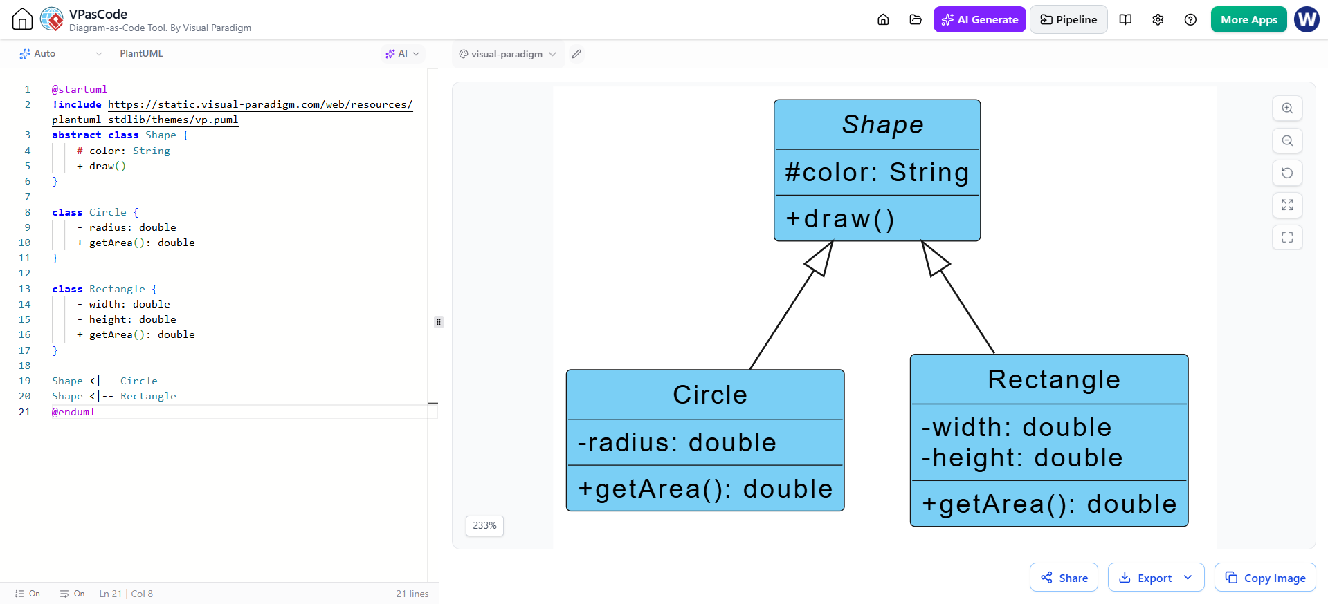
Using tools like Visual Paradigm, teams can leverage VPasCode to streamline the transition from abstract design to concrete implementation. This tutorial breaks down the differences between these diagrams and demonstrates how to model an e-commerce system effectively.
1. The Class Diagram: The System Blueprint
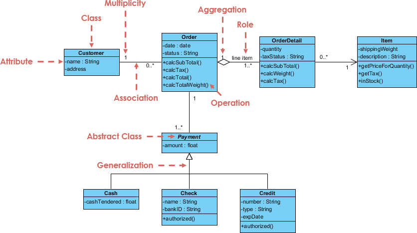
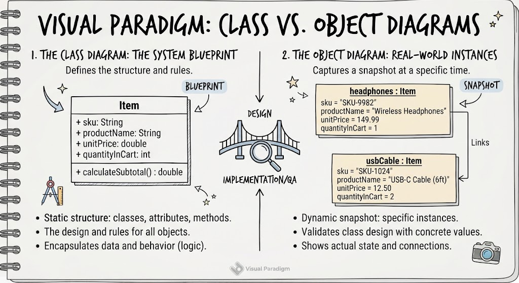
The Class Diagram is the backbone of an object-oriented system. It is a static structure diagram that describes the system’s classes, their attributes, operations (methods), and the relationships among objects. Think of this as the architectural blueprint for a building; it defines the structure and rules but does not contain the furniture.
Core Components of a Class
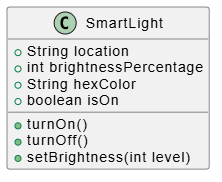
When modeling a class, such as an Item in an e-commerce shopping cart, you define the following elements:
- Class Name: Appears at the top of the class box, usually bolded. It represents the category of objects (e.g., Item).
- Attributes: These are the variables that hold data. In our example, an item has a
sku,productName,unitPrice, andquantityInCart. - Operations: These are the methods or behaviors the class can perform. For an item, a critical behavior is
calculateSubtotal(). - Visibility: Denoted by symbols before attributes or methods:
+(Public): Accessible by external components.-(Private): Accessible only within the class.#(Protected): Accessible by the class and its subclasses.
Example: The E-Commerce Item Class
Below is the PlantUML code representing the blueprint for a product. This defines what any item must possess, regardless of what that item actually is.
@startuml
class Item { + String sku + String productName + double unitPrice + int quantityInCart + calculateSubtotal() : double } @enduml
Analysis of the Blueprint
This Item class encapsulates all necessary data for a shopping cart entry. The + signs indicate public visibility, meaning external components (like a Cart Manager) can access these properties directly. The calculateSubtotal() method demonstrates the principle of encapsulation; rather than having external code manually multiply price by quantity, the Item itself owns this responsibility. In Visual Paradigm, this PlantUML can be edited via VPasCode to instantly update the visual representation.
2. The Object Diagram: Real-World Instances
While class diagrams define structure, Object Diagrams capture a snapshot of the system at a specific moment in time. They show actual instances of classes with concrete values. This is invaluable for validating class designs against real-world scenarios and for debugging complex state interactions.
Core Components of an Object
To create an object diagram, we instantiate the class blueprint:
- Instance Specification: Written as
objectName : ClassName. The name is typically underlined to distinguish it from the class itself. - Concrete Values: Attributes are assigned specific runtime values (e.g.,
sku = "SKU-9982"). - Links: These represent actual connections between specific objects, as opposed to abstract associations found in class diagrams.
Example: Shopping Cart Snapshot
The following diagram shows two specific items currently residing in a user’s cart. This validates that our Item class blueprint can adequately represent real products.
@startuml
object "headphones : Item" as hp { sku = "SKU-9982" productName = "Wireless Headphones" unitPrice = 149.99 quantityInCart = 1 } object "usbCable : Item" as usb { sku = "SKU-1024" productName = "USB-C Cable (6ft)" unitPrice = 12.50 quantityInCart = 2 } @enduml
Analysis of the Snapshot
Notice how each object conforms strictly to the Item class definition but carries unique state. The headphones object has a quantity of 1, while the usbCable has 2. If we were to call calculateSubtotal() on the usbCable object, it would return 25.00.
Object diagrams like this are particularly useful during sprint planning or QA testing to verify that the data model handles edge cases (e.g., multiple quantities, decimal pricing) correctly before implementation.
Best Practices for Effective UML Modeling
To maximize the value of your diagrams in a development lifecycle, consider the following strategies:
- Start with Classes, Validate with Objects: Always design the class structure first, then create object diagrams to test whether the design holds up with realistic data.
- Don’t Over-Model: UML should clarify, not complicate. Only include attributes and methods relevant to the current design discussion.
- Leverage Tooling: Use tools like Visual Paradigm’s VPasCode to maintain synchronization between textual definitions and visual diagrams. This reduces drift and improves collaboration between architects and developers.
- Use Object Diagrams for Communication: When explaining system behavior to non-technical stakeholders or new team members, object diagrams with real data are often more intuitive than abstract class structures.
- Maintain Traceability: Link your UML diagrams back to user stories or requirements. Visual Paradigm supports requirement tracing, ensuring every modeled element serves a business purpose.
Conclusion
UML Class and Object Diagrams remain indispensable tools in modern software development, despite the rise of agile and lightweight methodologies. Class diagrams provide the architectural blueprint that ensures consistency and scalability, while object diagrams ground those abstractions in reality, validating designs against actual use cases.
By leveraging professional tooling like Visual Paradigm, teams can streamline the modeling process, maintain living documentation, and foster better communication across product, design, and engineering disciplines. Whether you’re designing a simple shopping cart or a complex enterprise system, mastering these two diagram types will significantly enhance your ability to translate ideas into well-structured, maintainable software.
Remember: good design isn’t about drawing perfect diagrams—it’s about thinking clearly, and UML is the language that makes that thinking visible.