In the complex world of Business Process Management Notation (BPMN), few elements are as critical for creating dynamic, real-world models as Intermediate Events. These events allow processes to pause, wait for external data, or react to timing constraints, bridging the gap between simple sequential tasks.
This tutorial dissects a classic business scenario: The Order Approval Workflow. We will explore the system architecture behind purchase orders, analyze the specific modeling concepts shown in the diagram, and provide a comprehensive walkthrough on how to build this exact flow using Visual Paradigm.
Understanding the Architecture: The Purchase Order Lifecycle
Before drawing a single line, it is essential to understand the business logic we are modeling. The “Order Approval Workflow” represents a control mechanism designed to prevent unauthorized spending.
The process begins with a trigger: a Purchase Order is generated. However, this is not an autonomous action. The system architecture requires a validation step. A manager must review the request and provide a signal of approval or rejection. This “waiting period” is the core architectural challenge that Intermediate Events solve.
Deconstructing the Diagram: Key Modeling Concepts
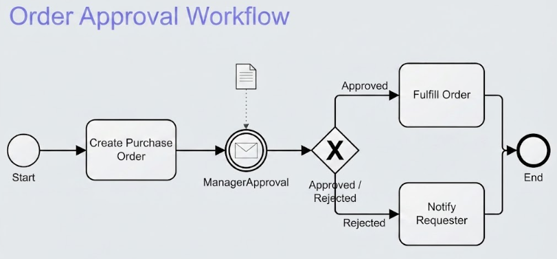
The provided diagram illustrates a robust control flow using standard BPMN 2.0 symbols. Let’s break down the specific components and their roles.
1. The Message Intermediate Catch Event
The most distinct element in this diagram is the circle with the envelope icon located between “Create Purchase Order” and the Gateway. This is a Message Intermediate Catch Event.
- Function: It acts as a synchronization point. The process execution halts here, waiting for an external signal.
- Context: In this scenario, the system is waiting for an email from the manager. The dotted arrow pointing to the event from the document icon visually represents this incoming communication.
- Contrast: Unlike a Task, which is an action performed by a human or system, an Intermediate Event is a state change or a trigger that modifies the flow.
2. The Exclusive Gateway (XOR)
Once the approval message is received, the flow hits a diamond shape marked with an ‘X’. This is an Exclusive Gateway.
- Logic: It acts as a decision point. The process can take only one path forward: either the order is “Approved” or it is “Rejected”.
- Branching: The labels “Approved” and “Rejected” on the outgoing arrows represent the specific conditions required to traverse that path.
Technical Walkthrough: Building the Model in Visual Paradigm
Now that we understand the theory, let’s apply it. Below are the precise steps to recreate this workflow in Visual Paradigm.
Step 1: Setting the Stage
Open Visual Paradigm and navigate to the diagram creation menu. Select New Diagram and choose BPMN Diagram. This initializes the canvas with the necessary BPMN palette.
Step 2: Creating the Sequence Flow
Begin with the standard linear flow:
- Drag a Start Event (circle) onto the canvas.
- Drag a Task (rounded rectangle) onto the canvas and name it “Create Purchase Order”.
- Connect the Start Event to the Task using the Sequence Flow tool.
Step 3: Implementing the Message Intermediate Event
This is the critical step for modeling the “wait” state.
- From the BPMN palette, locate the Intermediate Events section and drag an Intermediate Catch Event (a circle) onto the sequence flow connecting the Task to the next element.
- Right-click the event and select Set Event Type.
- In the dialog box, select Message. This automatically changes the icon to the envelope symbol.
- Open the Specification window (usually via F2 or the Properties panel).
- Set the Message Name to “ManagerApproval”. This links the diagram to the underlying data object or message definition.
Step 4: Adding the Decision Logic
Complete the workflow by adding the decision gate and final outcomes.
- Connect the Message Event to an Exclusive Gateway (Diamond shape).
- Create two outgoing Sequence Flows from the Gateway.
- Label the top path “Approved” and the bottom path “Rejected”.
- For the “Approved” path, add a Task named “Fulfill Order”.
- For the “Rejected” path, add a Task named “Notify Requester”.
- Finally, merge both paths into an End Event to signify the completion of the process.
Conclusion
By utilizing Intermediate Events and Gateways, you transform a static list of tasks into a responsive system architecture. This “Order Approval” model demonstrates how to handle external dependencies and decision-making logic effectively, ensuring your BPMN diagrams accurately reflect the complexity of real-world business operations.