Business Process Model and Notation (BPMN) is more than just a way to draw boxes; it is a language designed to describe the flow of work between different organizational entities. One of the most critical concepts in BPMN is understanding how to model communication between these entities. In this tutorial, we will explore the specific mechanics of Message Flows, using a classic “Order and Invoice” scenario between a Customer and a Shop.
Whether you are using Visual Paradigm or another modeling tool, understanding the distinction between internal process flow and external communication is the key to building accurate system architectures.
The Architecture of Pools and Lanes
Before drawing a single line, we must establish the boundaries of our process. In BPMN, a Pool represents a participant in a process—this could be a company, a department, or even a specific role like “Customer”.
- The Shop Pool: Represents the internal business processes of the retail entity.
- The Customer Pool: Represents the external actor who initiates the request.
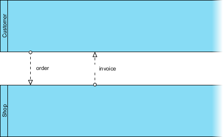
In the diagram provided, we see a horizontal layout. The Customer is at the top, and the Shop is at the bottom. These are two distinct “worlds.” In the strict logic of BPMN, a process inside the Shop cannot simply “flow” into the Customer’s headspace without a defined medium of communication.
Why You Can’t Use Sequence Flows
A common mistake for beginners is attempting to connect an activity in the Shop to an activity in the Customer using a standard Sequence Flow (a solid line with an arrow). However, Sequence Flows represent the logical order of steps within a single process.
If you try to connect a Shop element to a Customer element with a solid line, you are implying that the Customer is an internal task of the Shop, or that the two processes share the same control flow. This is semantically incorrect.
The Rule: To represent the movement of information (like a document, a signal, or a message) between two different participants (Pools), you must use a Message Flow.
Understanding the Message Flow Syntax
The Message Flow is visually distinct from a Sequence Flow. It is represented by a dashed line with specific arrowheads. Let’s break down the specific symbols used in our diagram to understand the data exchange.
1. The Message Start Event (The Circle)
In the diagram, notice the small open circle at the boundary of the Shop pool. This is a Message Start Event. It signifies that the process inside the Shop is waiting for an external trigger. It is “passive” until a message arrives.
2. The Message End Event (The Circle)
Conversely, at the boundary of the Customer pool, there is a small open circle connected to the dashed line. This represents a message being sent out or received. It acts as the interface between the internal process and the external world.
3. The Dashed Line
The dashed line itself represents the channel of communication. It does not represent the movement of a worker or a physical object (unless the message is a physical document like a fax), but rather the information itself. In our example, this could be a fax, an email, or a phone call.
Step-by-Step: Modeling the Order and Invoice Exchange
Let’s walk through the logic of the provided diagram, which illustrates a bidirectional exchange of information.
Step 1: The Order (Customer to Shop)
The process begins with the Customer. In a full diagram, the Customer would have an activity like “Place Order”. Once completed, they send the information to the Shop. This is drawn as a dashed line originating from the Customer’s boundary and terminating at the Shop’s Message Start Event. The label order identifies the payload of this message.
Step 2: The Invoice (Shop to Customer)
After the Shop receives the order and processes it (likely an internal sequence flow not shown in this snippet), they must notify the Customer. This is the reverse flow. A dashed line originates from the Shop and points to the Customer’s boundary. The label invoice indicates that the data being transferred is billing information.
Associations and Data Context
The prompt also mentions Associations and Data Associations. While the diagram focuses on the flow between pools, it is important to note how these relate to the diagram’s completeness.
- Associations: These are used to link text (like annotations or comments) to specific elements. They are typically solid lines.
- Data Associations: These connect data objects (like a physical document or a database record) to activities. They are often drawn with a small “data store” icon or a document shape.
In the context of Message Flows, the text labels “order” and “invoice” act as the Data Associations for the flow itself, defining what is actually traveling across the dashed line.
Implementing in Visual Paradigm
If you are using Visual Paradigm to recreate this architecture, the tool enforces these rules to maintain model integrity. When you drag a connector from the Customer pool to the Shop pool, the tool automatically recognizes that a Message Flow is required. If you attempt to use a Sequence Flow, Visual Paradigm will typically prevent the connection or warn you that the flow is invalid across pool boundaries.
Conclusion
Mastering the Message Flow is essential for any BPMN practitioner. It allows you to accurately model the “hand-off” points where one organization’s process ends and another’s begins. By using the dashed line and specific boundary events, you create a clear, unambiguous map of how information travels between the Customer and the Shop.