In the realm of Business Process Management (BPM), one of the most critical skills a modeler can develop is the ability to manage complexity through abstraction. When modeling complex systems like a bank’s loan approval workflow, drawing every single micro-action on the main diagram can lead to visual chaos and confusion. This is where the distinction between a Task and a Sub-Process becomes vital.
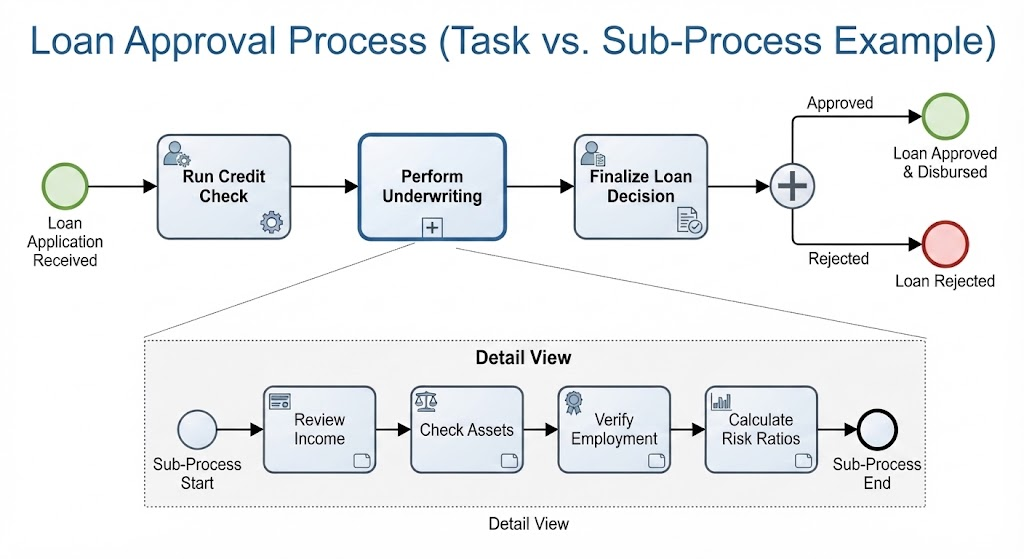
This tutorial analyzes the Loan Approval Process diagram to demonstrate how to effectively structure business logic using BPMN 2.0 standards. We will walk through the logic of abstraction, analyzing the “Run Credit Check” atomic task versus the complex “Perform Underwriting” sub-process.
The Core Concept: Granularity and Abstraction
The diagram illustrates a classic scenario: how much detail is enough? The answer depends on the audience and the specific system requirement. In BPMN, we have two primary ways to represent an activity:
- A Task: An atomic action. It is the smallest unit of work. It implies “Do this now” without needing to explain the internal steps. It is a black box that simply happens.
- A Sub-Process: A container for a group of activities. It represents a larger, complex phase of work that needs to be broken down for clarity. It allows us to hide complexity until the viewer chooses to “drill down.”
Visual Analysis of the Loan Approval Workflow
Let’s break down the “Loose” or “High-Level” view of the process shown in the top half of the diagram. This view represents the System Architecture of the decision-making flow.
1. The Trigger: Loan Application Received
The process begins with a Start Event (the green circle). This is the trigger that initiates the workflow. In a real-world scenario, this could be a user clicking “Submit” on a web portal or an API receiving a payload from a third-party aggregator.
2. The Atomic Task: Run Credit Check
The first major step is labeled “Run Credit Check.” Notice the small gear icon in the corner? This indicates a Service Task.
Why is this modeled as a Task and not a Sub-Process?
- Atomicity: For the bank’s internal logic, checking a credit score is a single action. It calls an external API, receives a score, and returns a boolean or numeric value.
- Abstraction: The bank does not need to model the internal steps of the credit bureau’s database query. To the loan system, this is a simple “call and response.”
3. The Complex Phase: Perform Underwriting
The next step is the “Perform Underwriting” block. Unlike the credit check, this is a heavy, multi-faceted operation. It is modeled as a Collapsed Sub-Process (indicated by the plus sign in the corner).
If we were to draw all the underwriting steps on the main line, the diagram would become a long, unreadable spaghetti of boxes. Instead, we encapsulate the complexity here.
Drilling Down: The Detail View
The bottom section of the diagram, labeled “Detail View,” is the “expanded” version of the Perform Underwriting sub-process. This is where the modeling shifts from high-level architecture to operational logic.
Step-by-Step Breakdown
- Sub-Process Start: The workflow enters the detailed view. This is the entry point for the logic defined inside the “Underwriting” phase.
- Review Income: The system pulls data regarding the applicant’s salary, tax returns, or bank statements. This is likely a manual or semi-automated task.
- Check Assets: A parallel check to verify net worth, real estate holdings, or investment accounts.
- Verify Employment: Confirming the stability of the applicant’s job history.
- Calculate Risk Ratios: The system takes the inputs from the previous three steps to perform a mathematical analysis (e.g., Debt-to-Income ratio).
- Sub-Process End: Once the calculations are complete, the sub-process returns control to the main flow. It outputs a result (e.g., “Risk Level: High” or “Risk Level: Low”).
Decision Making and Outcomes
Once the underwriting is complete, the process moves to the “Finalize Loan Decision” task. This is followed by a Parallel Gateway (the circle with the plus sign). In this specific diagram, the gateway appears to be acting as a split point for the outcome, although logically, a decision (Exclusive Gateway) is often used for “Approved vs. Rejected” based on the risk calculation.
The diagram concludes with two distinct end events:
- Loan Approved & Disbursed (Green Circle): The success path where funds are released.
- Loan Rejected (Red Circle): The failure path where the application is terminated.
Key Takeaways for System Architects
When designing your own BPMN diagrams, remember the lesson from this example: Model what is necessary, but hide what is not.
Use Tasks for simple, atomic interactions (like API calls or form fills). Use Sub-Processes when a phase of the workflow contains enough complexity to warrant its own separate diagram or tab. This approach keeps your high-level architecture clean and your detailed logic accessible.