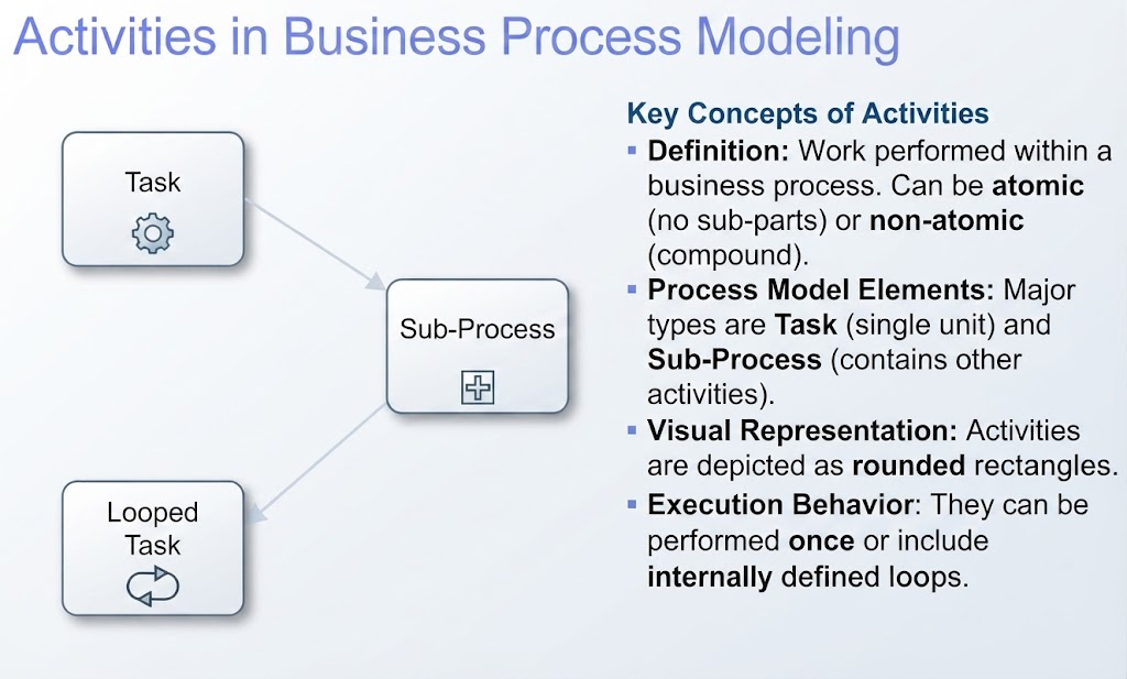
In the world of Business Process Management (BPM), clarity is king. Whether you are mapping out a simple approval workflow or designing a complex enterprise integration, the ability to break down work into understandable chunks is essential. This tutorial delves into the core of BPMN 2.0—the Activity—and explores how to model work effectively using atomic tasks, compound sub-processes, and iterative loops.
Understanding the Anatomy of an Activity
At its foundation, an Activity represents work performed within a business process. Visually, these are always depicted as rounded rectangles. However, not all activities are created equal. To model a process accurately, you must choose the right granularity for your work units.
1. The Task (Atomic Activity)
A Task is the smallest unit of work in a BPMN diagram. It is considered atomic, meaning it is not broken down into further detail within the current diagram. It represents a single step or action.
- Visual Representation: A simple rounded rectangle. In Visual Paradigm, this often features a gear icon or a specific user icon depending on the type.
- Usage Strategy: Use a Task when the step is self-explanatory. For example, “Validate Data” or “Review Application” implies a single action that doesn’t require further explanation on the current page.
2. The Sub-Process (Compound Activity)
When a step involves complex logic that would clutter your diagram if drawn out in detail, you use a Sub-Process. This is a non-atomic activity that acts as a container for a set of other activities, flows, and events.
- Visual Representation: A rounded rectangle containing a small plus sign (+) marker at the bottom center.
- Usage Strategy: Use a Sub-Process to “zoom out” on the main view. For instance, a step named “Onboard New Employee” might involve hiring, IT setup, and training. Instead of drawing all those steps on the main chart, you group them inside a Sub-Process.
3. Looping Behavior
Real-world business processes are rarely strictly linear; they often require iteration. Activities can be configured to repeat until a specific condition is met.
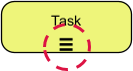
- Visual Representation: A rounded rectangle containing a circular arrow icon at the bottom.
- Usage Strategy: This is crucial for scenarios like “Review Document” where the reviewer might request changes multiple times before the document is finally approved.
Technical Implementation: Modeling in Visual Paradigm
To translate these concepts into a technical diagram, we will use Visual Paradigm, a robust tool for BPMN 2.0 modeling. Follow this workflow to implement the concepts described above.
Step 1: Setting Up the Canvas
Begin by launching Visual Paradigm and creating a new BPMN Diagram. You will immediately see the BPMN Shape Palette on the left-hand side. Familiarize yourself with the sections: Flow Objects (where your activities live), Connecting Objects, and Swimlanes.
Step 2: Creating a Standard Task
To represent your atomic unit of work:
- Drag a Task shape from the palette onto your canvas.
- Double-click the shape to rename it (e.g.,
Validate Data). - Pro Tip: In the resource catalog, you can change the task type to specific variations like User Task (indicating a human actor) or Service Task (indicating an automated system). This is done by right-clicking the shape and selecting Type > User Task, which adds a small user icon for semantic clarity.
Step 3: Creating a Sub-Process
To encapsulate complex logic:
- Drag a Sub-Process shape onto the canvas. Note that it automatically includes the + marker.
- You have two options for how to handle the internal details:
- Option A (Collapsed): Keep the + visible. This keeps your main diagram clean. You can double-click the shape to navigate to a child diagram where you model the internal steps.
- Option B (Expanded): Right-click the Sub-Process and select Expand. The box will grow larger, allowing you to drag other tasks and gateways directly inside it. This is useful for showing detail without switching views.
Step 4: Adding Loops
To indicate iterative behavior:
- Select an existing Task or Sub-Process.
- Look for the Loop Marker resource in the popup resource catalog (or right-click to look for markers).
- Select the Loop marker (circular arrow).
- Visual Paradigm will update the shape to indicate that this work is repetitive. You can configure the loop condition (Standard Loop vs. Multi-Instance) in the shape’s specification window to define exactly how the iteration behaves.
Summary
By mastering the distinction between Tasks, Sub-Processes, and Looped Tasks, you can create BPMN diagrams that are not only visually clean but also technically precise. Whether you are defining a single atomic action or a complex, iterative workflow, these tools provide the structure needed to map real-world business logic accurately.