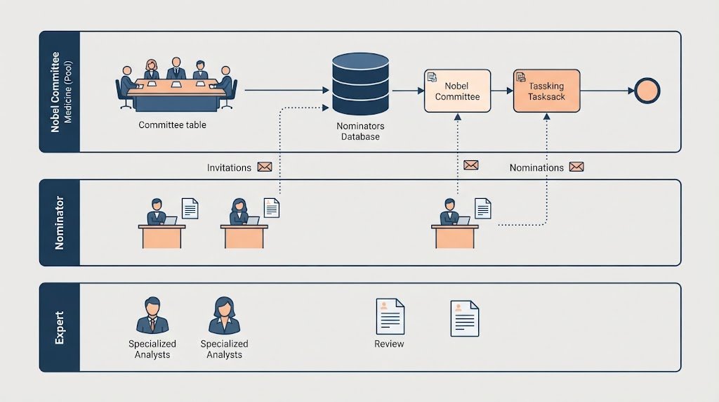
In the world of business process management, clarity is king. Visual Paradigm, a leading tool for systems modeling, allows organizations to translate complex real-world scenarios into precise, executable diagrams. The image provided showcases a sophisticated BPMN 2.0 (Business Process Model and Notation) diagram titled “The Nobel Prize.” This specific diagram models the intricate workflow for selecting medical nominees, demonstrating how different actors interact through data, decisions, and communications.
This tutorial will walk you through the architecture of this diagram, breaking down the swimlanes, the flow of information, and the technical symbols used to represent data persistence and decision logic.
1. The Architecture: Swimlanes and Responsibility
The most striking feature of this BPMN diagram is its use of Swimlanes (labeled as Lanes within a Pool). This architectural choice is critical for defining “Who does What?”
- The Main Pool: Nobel Committee Medicine – This is the central governing body. It holds the majority of the process logic, acting as the hub that coordinates the entire nomination cycle.
- The Nominator Lane – Located at the bottom left, this lane represents the external experts or individuals invited to submit names. They are responsible for the initial identification of candidates.
- The Expert Lane – Located at the bottom right, this lane represents specialized reviewers who may be called upon if the committee requires deeper technical assessment.
By separating these lanes, the diagram immediately clarifies that the “Nobel Committee” initiates the process but relies on external inputs to proceed.
2. Step-by-Step Process Flow Analysis
Let’s trace the “As-Is” process flow from the start event to the final selection, observing how the diagram handles parallel and conditional logic.
Phase 1: Initiation and Invitation
The process begins on the left side of the “Nobel Committee Medicine” lane with a Start Event labeled “September Year n-1.” This indicates the annual cycle of the nomination process.
- Action: The committee performs the task “Send Nomination Form.”
- Data Retrieval: Before sending, the committee accesses a data store labeled “Nominators.” This cylinder icon represents a database or repository containing the contact list of qualified individuals.
- Communication: A Message Flow (the dotted line with an envelope icon) travels from the Committee lane down to the “Nominator” lane. This signifies an external communication, not just a handoff within the same organization.
Phase 2: The Nomination Loop
Once the Nominators receive the invitation, their workflow activates:
- Identify Potential Nominee(s): The nominator performs the task of finding a suitable candidate.
- Send Nominee Completed Form(s): The nominator returns the data. A message flow travels back up to the main committee lane.
- Storage: Upon arrival, the data is saved into a data store labeled “Completed Nomination Forms.” This ensures the committee has a record of all submissions for later analysis.
Phase 3: Selection and Expert Review
Back in the main “Nobel Committee Medicine” lane, the committee performs “Collect Completed Forms” followed by “Screen & Select Preliminary Candidates.”
Here, the process introduces a critical decision point:
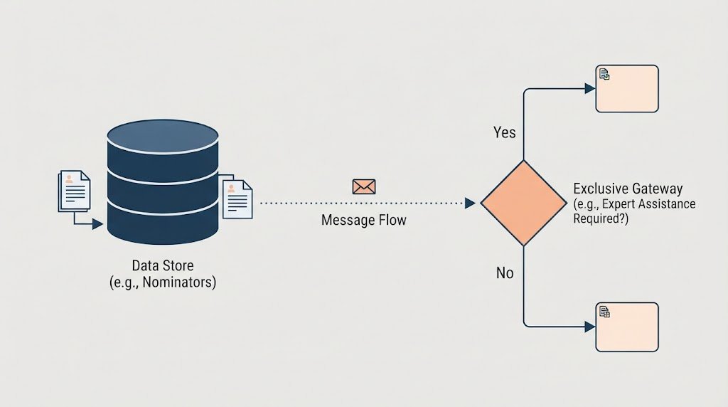
- Decision: The task “Determine Need for Expert Assistance” leads to a Exclusive Gateway (the orange diamond). The text below asks: “Expert Assistance Required?”
- The “Yes” Branch: If the answer is yes, the process splits to the “Expert” lane. The experts perform “Assess Candidates Work” and send back an “Assessment Report.” This report loops back into the main flow to be stored in the “Selected Preliminary” data store.
- Final Output: Once all data is gathered, the committee performs the final task: “Send List of Selected Preliminary Candidates.”
3. Technical Symbols and Concepts Explained
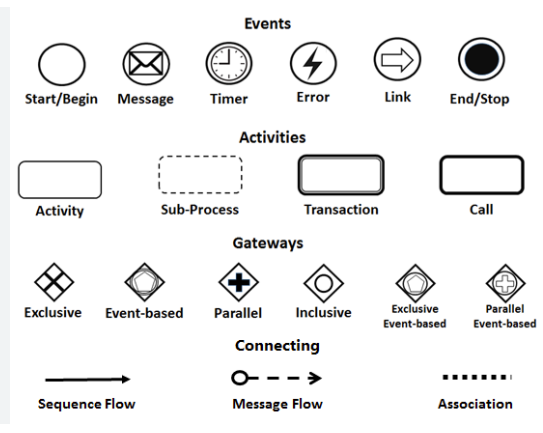
To fully understand the system architecture presented in Visual Paradigm, one must decode the specific BPMN symbols used:
Data Stores (Cylinders)
The diagram utilizes multiple cylinder icons (e.g., “Nominators,” “Completed Nomination Forms”). In BPMN, these represent information repositories. They show that the process is not just a linear sequence of tasks but involves the storage and retrieval of data. This is crucial for audit trails and ensuring data integrity.
Message Flows (Dotted Lines with Envelopes)
Unlike solid lines which represent sequence flow (one task leading to the next), the dotted lines crossing between swimlanes are Message Flows. They indicate the exchange of information between different participants (the Committee and the Nominators/Experts). This distinction is vital for understanding system boundaries.
The Gateway (Diamond)
The orange diamond labeled “Expert Assistance Required?” is a Gateway. It acts as a traffic controller. In this architecture, it ensures that the process doesn’t proceed to the final selection until the committee has decided whether additional expert validation is necessary. This represents a logical filter in the system.
Conclusion
This BPMN diagram is more than just a chart; it is a complete specification of a business system. It defines the data requirements (databases for nominators and candidates), the communication protocols (message flows), and the decision logic (gateways). By using tools like Visual Paradigm, organizations can simulate these flows to identify bottlenecks—such as the potential delay caused by waiting for expert assessments—before the process is ever executed in the real world.