


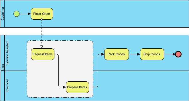
In the world of business process modeling, clarity is king. A complex workflow like order fulfillment can easily become a tangled web of confusion if not structured correctly. This tutorial breaks down a specific BPMN (Business Process Model and Notation) diagram, demonstrating how to visualize a complete order cycle using swimlanes, message flows, and the powerful grouping notation.
Understanding the Architecture: Swimlanes and Responsibilities
The first thing to notice in this diagram is the horizontal structure. In BPMN, these are called swimlanes (or partitions). They are the backbone of process architecture because they answer the question: “Who is responsible for this task?”
- Customer Lane: The process begins here. The customer initiates the flow.
- Service Assistant Lane: This is the central hub of the operation. The assistant manages the interaction and the final packaging.
- Shop & Inventory Lanes: These represent the backend logistics. They handle the physical retrieval and stocking of goods.
By separating these activities, the diagram immediately clarifies that while the Customer starts the process, the actual work is distributed among the Service Assistant and the Inventory team.
Step-by-Step: Tracing the Order Fulfillment Flow
Let’s walk through the lifecycle of an order as depicted in this diagram, moving from the top left to the bottom right.
1. The Initiation (Start Event)
The process kicks off with a green circle in the Customer lane. This is a Start Event. It signifies the trigger for the entire workflow: a customer deciding to buy something.
2. Placing the Order
The first task is Place Order. This is a standard task (rounded rectangle) performed by the customer. Once this is done, the process moves to the backend.
3. The Handoff (Message Flow)
Notice the dashed line with an open arrow connecting Place Order to the next step. In BPMN, this is a Message Flow. It indicates communication between different participants (in this case, the Customer and the Service Assistant). It implies that the “Order” is being transmitted or received, bridging the gap between the two swimlanes.
4. Retrieving the Goods
Once the Service Assistant receives the order, they perform Request Items. This triggers a physical action in the Inventory lane: Prepare Items. The arrow indicates that the Service Assistant requests the items, and the Inventory team prepares them for handover.
5. Fulfillment and Completion
Once the items are ready, the flow returns to the Service Assistant for Pack Goods. Finally, the task Ship Goods is executed, leading to a red circle—an End Event—signaling that the process is successfully finished.
Deep Dive: The Power of BPMN Groups
The most distinct visual feature in this diagram is the large, dashed-line box surrounding Request Items and Prepare Items. In technical modeling, this is known as a BPMN Group.
Unlike a sub-process, a Group does not have its own internal logic or flow; it is purely a visual annotation. Here is why it is used here:
- Visual Clustering: The group visually clusters the “Retrieval” phase. It tells the reader that “Request Items” and “Prepare Items” belong together logically, even though they happen in different swimlanes.
- Documentation Context: As noted in BPMN standards, groups are used for documentation purposes. It highlights a specific domain (likely Inventory Management) without breaking the linear flow of the main process.
- Complexity Reduction: If the process were much more complex, a group allows us to group several sub-tasks under a single label (like “Inventory Check”) without drawing a full sub-process box, keeping the diagram clean.
Conclusion
This diagram serves as an excellent example of how BPMN creates a bridge between technical requirements and business operations. By using swimlanes, we define roles; by using message flows, we define communication; and by using groups, we define logical context. Whether you are using a tool like Visual Paradigm or drawing by hand, mastering these elements is key to creating professional, understandable process maps.
Related posts:
 Understanding Mortgage Application Flows with BPMN
 Mastering BPMN Collaboration: A Guide to Cross-Platform Modeling with Visual Paradigm Online
 Mastering BPMN Markers: A Technical Deep Dive into E-Commerce Order Fulfillment
 Mastering BPMN Public Processes: An Architectural Guide to External Interfaces