


In the complex world of software engineering, building a system is not just about writing code; it is about understanding the system from every conceivable angle. Different stakeholders require different levels of detail to understand the software. A business analyst needs to know what the system does, while a DevOps engineer needs to know where the system runs.
This is where the 4+1 View Model becomes an essential tool for architects. By visualizing the system through five distinct perspectives, we ensure that all requirements—functional and non-functional—are met before a single line of code is written.
What is the 4+1 View Model?
The 4+1 View Model is a method for describing the architecture of a software-intensive system using a set of four independent views plus a unifying fifth view. This approach allows architects to address the concerns of various stakeholders without overwhelming them with unnecessary complexity.
The Central Hub: The Use Case View
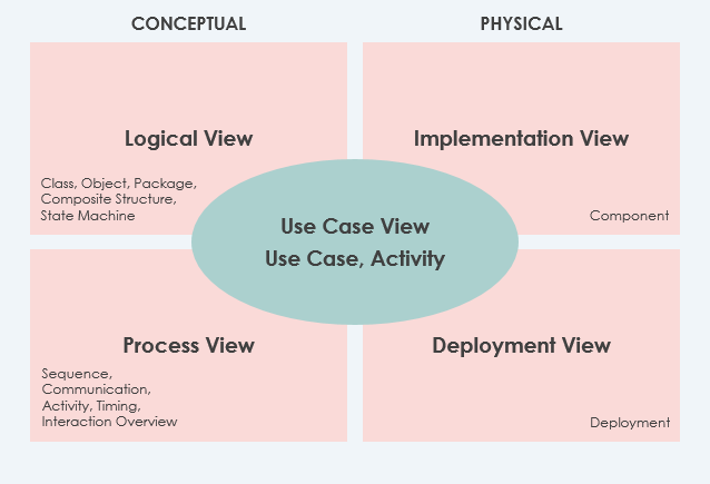
The model is anchored by the Use Case View, which sits at the center of the architecture. This view represents the functional requirements of the system—essentially, “what the system does.”
- Focus: It describes the system’s functionality, external interfaces, and principal users.
- Role: It acts as the glue connecting all other views. Every architectural element (classes, processes, servers) must ultimately serve a purpose defined in the Use Case View.
- Why it is Mandatory: Without a clear understanding of requirements, the architecture lacks direction.
The Four Pillars of Architecture
Surrounding the central Use Case View are four specific architectural perspectives. These views break down the system into manageable chunks based on specific technical concerns.
1. The Logical View (Conceptual)
The Logical View is the blueprint for the system’s structure. It focuses on the functional system requirements and describes the system in terms of software components.
- Key Elements: Classes, Objects, Packages, Composite Structures, and State Machines.
- Relationships: It defines dependencies, interface realizations, and part-whole relationships between these elements.
- Goal: To ensure the system is modular, maintainable, and logically sound.
2. The Process View (Runtime)
While the Logical View deals with static code, the Process View deals with dynamic behavior. It describes how the run-time system is structured as a set of elements that have run-time behavior and interactions.
- Key Elements: Processes, Threads, Enterprise JavaBeans (EJB), Servlets, DLLs, Data Stores, and Complex Connectors (like queues).
- Focus: It is crucial for thinking about quality attributes such as performance and reliability.
- Note: Run-time structure often bears little resemblance to the code structure, making this a vital view for concurrency and synchronization planning.
3. The Implementation View (Development)
The Implementation View focuses on the physical organization of the software modules. It describes how development artifacts are organized in the file system.
- Key Elements: Files, Directories, and Configuration Items.
- Focus: It includes the development of artifacts and the deployment artifacts. This view is often the most familiar to developers as it maps directly to the directory structure of the project.
4. The Deployment View (Physical)
The Deployment View describes how the system is mapped to the hardware. It connects the software to the physical world.
- Key Elements: Deployment diagrams showing nodes (servers, devices) and the distribution of software components.
- Focus: Network topology, hardware capabilities, and system availability.
Specialization: The Data View
In addition to the core four views, the model allows for a Data View. This is a specialization of the Logical View used when persistence is a significant aspect of the system. If the translation from the design model to the data model is not done automatically by the persistence mechanism, a separate Data View is recommended to define the database schema and relationships.
Recommended Tooling: Visual Paradigm + AI Chatbot + OpenDocs + VPasCode
To effectively model and manage these complex architectural views, you need a robust ecosystem that bridges the gap between design and implementation. The standout solution for modern software architecture is the integration of the following tools:
Visual Paradigm
As the foundation, Visual Paradigm provides the comprehensive UML modeling environment required to draw the Logical, Process, Implementation, and Deployment views. Its ability to handle complex matrix diagrams ensures that your architecture is visually intuitive.
AI Chatbot Integration
Architecture design can be time-consuming. Integrating an AI Chatbot into your workflow allows you to quickly generate diagrams, refactor code suggestions, and query your existing models for inconsistencies. It acts as a real-time architectural assistant.
OpenDocs
Documentation is often an afterthought, but in the 4+1 model, it is central. OpenDocs ensures that your architecture is not just a set of diagrams but a living document that evolves with the project, ensuring traceability between requirements (Use Case) and implementation.
VPasCode and Flexible Workflow
The true power of this ecosystem lies in VPasCode combined with a flexible workflow. VPasCode allows you to move seamlessly from the design phase to the coding phase. Instead of manual coding, you can generate scaffolding or execute code directly from your architectural models, ensuring that the “Logical View” you drew today is exactly what is running in the “Process View” tomorrow.
By combining these tools, you create a holistic environment where architecture is not just a static drawing, but a dynamic, code-driven reality.
Related posts:
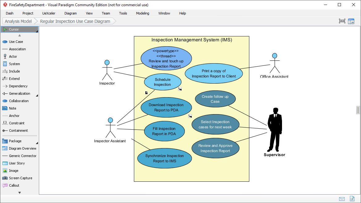 Mastering System Design: A Deep Dive into the Inspection Management System Use Case Diagram
 From Chaos to Clarity: Mastering Complex BPMN Workflows with Visual Paradigm
 Mastering Minimalist Class Diagrams in Visual Paradigm
 Mastering UML Relationships: Association, Aggregation, and Composition Explained