The Anatomy of a Transaction System
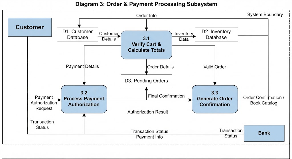
When we look at complex systems like e-commerce platforms, it is easy to get lost in the sheer volume of code and database tables. However, if you zoom out, the logic often boils down to a simple sequence: receiving information, processing it, and sending it back out. In Visual Paradigm, we represent this logic using Data Flow Diagrams (DFDs). Let’s walk through Diagram 3: Order & Payment Processing Subsystem to see how these pieces fit together.
Identifying the Actors and Boundaries
Every DFD starts by defining the system boundary—the dashed box that separates what the computer does from what humans or other systems do. Inside this boundary, we have our core business logic; outside, we have the actors.
- External Entities: Notice the blue rectangles labeled “Customer” and “Bank.” These are not part of your software but interact with it. The Customer initiates the action, while the Bank acts as an external validator for money.
- Data Stores: Represented by open-ended lines, such as D1. Customer Database, D2. Inventory Database, and D3. Pending Orders. These are where the system holds its memory.
Step-by-Step Process Flow
To understand the lifecycle of an order, let’s trace the path of data from the moment a customer clicks “Buy” to the moment they receive confirmation.
Phase 1: Verification and Calculation (Process 3.1)
The journey begins at the top with Process 3.1: Verify Cart & Calculate Totals. This process is the gatekeeper of the system. It doesn’t just calculate numbers; it validates them against reality.
- Input: It receives “Order Info” from the Customer and pulls “Customer Details” from the Customer Database (D1).
- Validation: Crucially, it sends a request for “Inventory Data” to the Inventory Database (D2). This ensures that before we promise anything, the item actually exists.
- Output: If everything checks out, it produces “Order Details” and sends them to the next stage.
Phase 2: Financial Authorization (Process 3.2)
Once the cart is verified, the system moves to Process 3.2: Process Payment Authorization. Here, the focus shifts from goods to currency.
- Interaction: The system takes “Payment Details” (which likely came from the Customer) and prepares a “Payment Authorization Request.”
- External Handshake: This request is sent out of the system boundary to the Bank. This represents the API call or secure handshake required to verify funds.
- Feedback Loop: The Bank returns a “Transaction Status.” This result is critical—it tells the system whether to proceed or abort the transaction.
Phase 3: Finalizing the Order (Process 3.3)
The final step is Process 3.3: Generate Order Confirmation. This process only triggers if the payment was successful.
- Consolidation: It takes the “Valid Order” details from the first process and the “Authorization Result” from the second.
- Storage: Before confirming to the user, it writes a record to D3. Pending Orders. This ensures the order is tracked internally even before the shipping department gets involved.
- Completion: Finally, the system sends “Order Confirmation / Book Catalog” back to the Customer, closing the loop.
Why Structure Matters
This diagram demonstrates why separating concerns is vital in system design. By splitting the logic into three distinct processes, we ensure that inventory checking doesn’t block payment processing, and payment errors don’t clutter the order records. Using tools like Visual Paradigm allows you to visualize these dependencies clearly, making it easier to spot bottlenecks—like a missing data store or a circular dependency—before writing a single line of code.
Key Takeaways
- System Boundaries: Always define what is inside your application versus what is external (like the Bank).
- Data Integrity: Notice how the Inventory Database is checked early to prevent selling non-existent items.
- Sequential Logic: Complex systems are often just a series of smaller steps: Verify -> Authorize -> Confirm.