Introduction to Diagram-as-Code
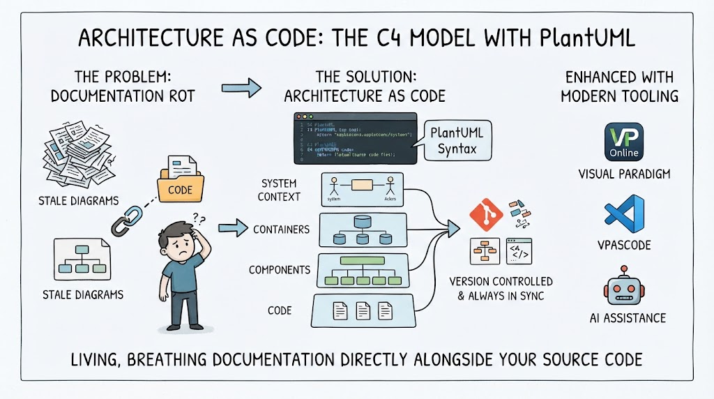
In the world of software architecture, capturing high-level interactions is often the first step in understanding complex systems. While traditional drawing tools are common, there is a growing preference for defining diagrams through code—a practice known as “Diagram-as-Code.” This approach allows architects to version control their designs and iterate quickly.
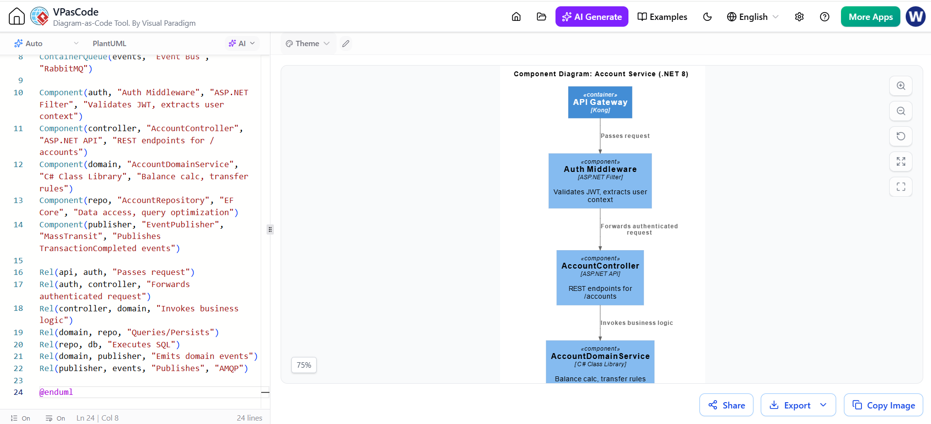
In this tutorial, we will look at a practical example: an Internet Banking System. We will walk through the specific code required to generate a System Context diagram using VPasCode, the PlantUML interface provided by Visual Paradigm.
Setting the Stage with Layout Directives
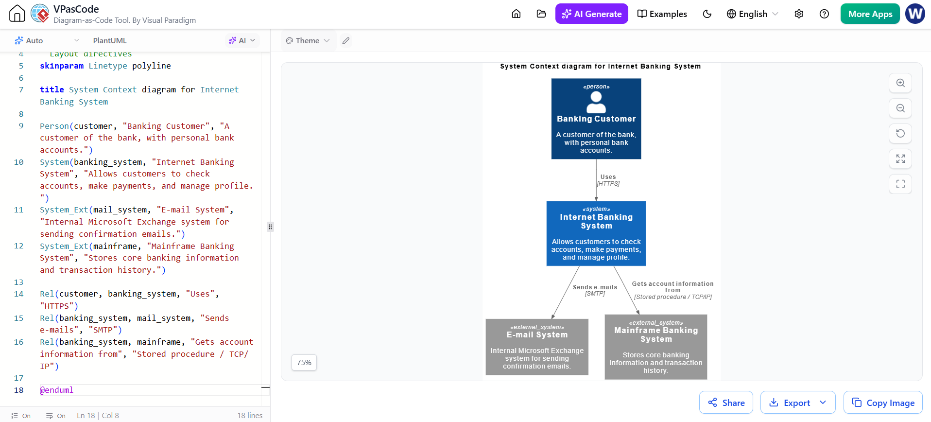
Before defining any actors or systems, it is important to establish the visual style of our diagram. In the code editor on the left side of the screen, you can see layout directives that control the appearance.
skinparam Linetype polyline: This command ensures that the connecting lines between components appear as polylines (lines with right-angle bends) rather than straight diagonal lines, which often results in a cleaner, more organized look.
Defining the Core Components
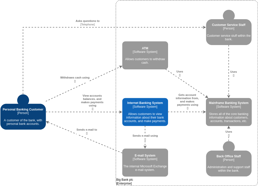
A System Context diagram focuses on the system itself and its immediate environment. To build this, we need to define four distinct elements using specific keywords:
1. The Human Actor
We start with the primary user of the application. Using the Person keyword, we define the customer:
Person(customer, "Banking Customer", "A customer of the bank, with personal bank accounts.")This creates the top node in your diagram, representing the individual initiating the interaction.
2. The Primary System
Next, we define the central application. Here, we use the System keyword to represent the Internet Banking platform:
System(banking_system, "Internet Banking System", "Allows customers to check accounts, make payments, and manage profile.")This component sits at the center of the context, acting as the bridge between the user and backend data.
3. External Systems
Banks rarely operate in isolation. They rely on other services. For those external dependencies, we use the System_Ext keyword. In our scenario, we have two critical external systems:
- Email System: An internal Microsoft Exchange system used for sending notifications.
- Mainframe Banking System: The legacy core that stores transaction history and account details.
Mapping the Interactions (Rel)
Once the boxes are defined, the real story begins with the relationships. We use the Rel (Relationship) keyword to draw arrows and describe the flow of data.
Customer Interaction
The customer accesses the banking system over a secure connection. The relationship is defined as:
Rel(customer, banking_system, "Uses", "HTTPS")This clearly indicates that the user interacts via the HTTPS protocol.
Internal Communications
The Internet Banking System then communicates with the external systems. Notice how we specify the protocols used:
- To send emails, the system uses SMTP.
- To retrieve account information, it connects to the Mainframe using a Stored procedure / TCP/IP mechanism.
Summary of Key Learnings
By following this workflow in VPasCode, you have successfully modeled a standard banking architecture. You learned how to:
- Use PlantUML syntax within Visual Paradigm’s interface.
- Differentiate between human actors (
Person) and technical systems (System,System_Ext). - Define clear relationships and protocols to explain how data flows through the ecosystem.
This method provides a rapid way to visualize complex integrations without getting bogged down in manual drawing.