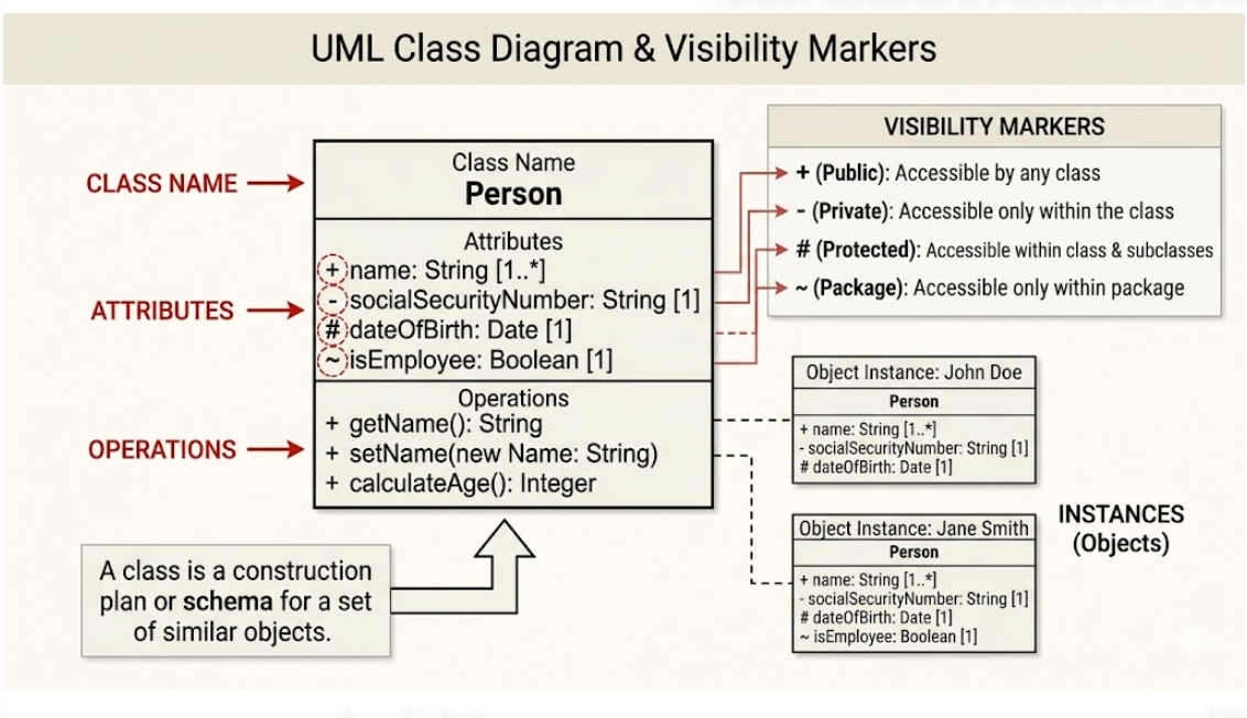
Object-Oriented Design (OOD) relies heavily on the ability to visualize the structure of a system before writing a single line of code. The Unifying Modeling Language (UML) Class Diagram is the primary tool used for this purpose. It serves as the blueprint for software, defining not just what data exists, but how that data interacts through behavior.
In this tutorial, we will dissect the anatomy of a Class Diagram, exploring the critical distinction between a Class (the blueprint) and an Instance (the actual object), while learning how to precisely control data access using Visibility Markers.
1. The Blueprint: Understanding the Class Structure
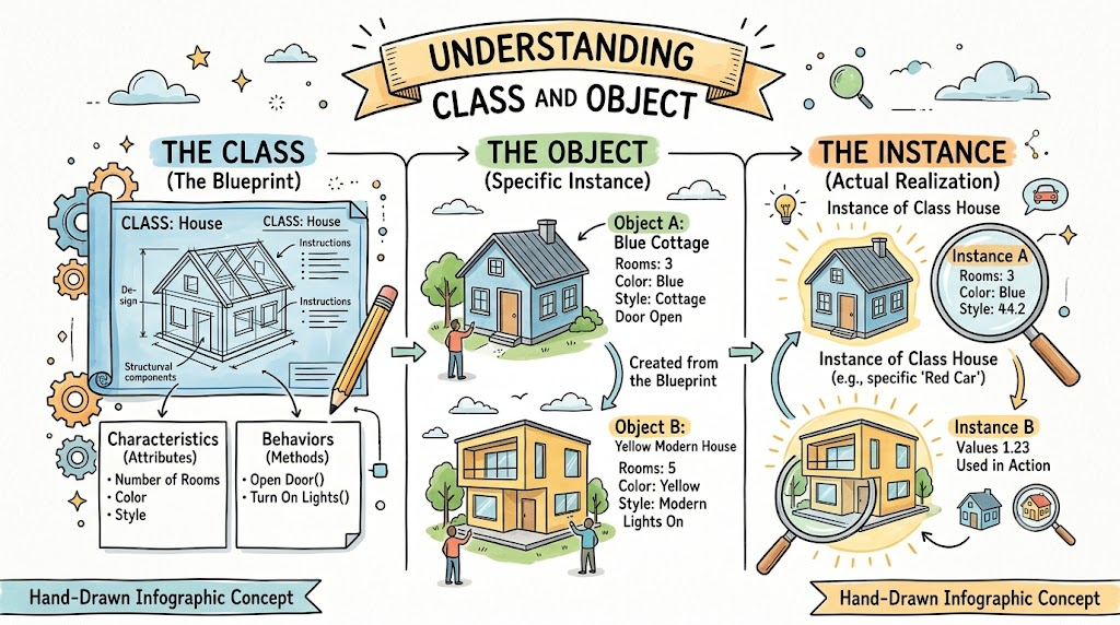
At the heart of any UML Class Diagram is the Class itself. Think of a class not as a living, breathing entity, but as a construction plan or schema. Just as an architect’s blueprint defines the rooms, windows, and wiring of a house without actually building it, a Class definition defines the properties and behaviors available to objects.
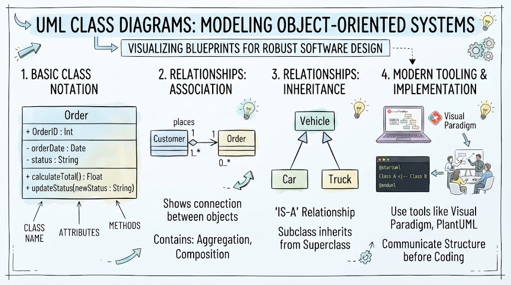
A standard Class diagram is visually represented as a rectangle divided into three distinct compartments:
- Top Compartment: Contains the Class Name.
- Middle Compartment: Lists the Attributes (data).
- Bottom Compartment: Lists the Operations (behavior).
The Class Name
The top compartment holds the identifier for the class, such as Person. This name represents the category of objects. It is the standard identifier that developers use to instantiate new objects in the code.
The Attributes (Structural Characteristics)
The middle compartment describes the structural characteristics of the class. These are the variables that store data about the object. In the diagram, you will notice a specific syntax used to define these attributes:
- Visibility Marker: A symbol indicating who can see this data.
- Attribute Name: The identifier for the variable (e.g.,
name). - Type: The data type (e.g.,
String,Date). - Multiplicity: Often shown in brackets (e.g.,
[1..*]), indicating how many values this attribute can hold.
The Operations (Behavior)
The bottom compartment defines the behavior or services an object provides. These are essentially methods or functions that the object can perform. The syntax here is similar to attributes but includes parameters and a return type:
- Name: The method name (e.g.,
getName). - Parameters: Optional input data (e.g.,
(new Name: String)). - Return Type: The data type returned by the method (e.g.,
: String).
2. The Power of Visibility Markers
One of the most critical concepts in object-oriented design is Encapsulation. This is the practice of restricting access to certain components of an object. In UML, this is achieved using specific Visibility Markers placed before the attribute or operation name.
As illustrated in our diagram, there are four standard markers:
1. Public (+)
The plus sign indicates that an attribute or operation is accessible by any class. This is the most open level of access, allowing other parts of the system to read or modify the data freely.
2. Private (-)
The minus sign indicates that an attribute is accessible only within the class itself. This is crucial for protecting sensitive data. For example, a socialSecurityNumber is typically marked as private to ensure that no other class can directly modify or view it without going through specific, secure methods.
3. Protected (#)
The hash symbol indicates that the element is accessible within the class and its subclasses. This is primarily used in inheritance hierarchies, allowing child classes to access specific data from the parent class while keeping it hidden from the rest of the world.
4. Package (~)
The tilde symbol indicates package-level access. This means the attribute is accessible to any class that resides within the same package (a grouping of related classes), but is hidden from classes outside that package.
3. From Blueprint to Reality: Classes vs. Instances
It is vital to distinguish between the Class (the definition) and the Instance (the object).
If the Class is the blueprint for a house, an Instance is the actual house built from that blueprint. In software terms, when you define a class named Person, you haven’t created a person yet. You have simply defined what a person looks like in your system.
To create a specific entity, you create an Instance. Notice in the diagram how the “Object Instance” boxes (like John Doe and Jane Smith) mirror the structure of the main Class box. They contain the same attributes, but crucially, they hold concrete values rather than just types.
- Class: Defines
name: String. - Instance (John Doe): Holds
name: "John Doe".
This relationship allows developers to create hundreds or thousands of unique objects based on a single, efficient definition. Every Person object in the system will have a socialSecurityNumber and a dateOfBirth because they are all constructed from the same Class schema.
Summary
UML Class Diagrams provide a standardized way to map out the static structure of a system. By mastering the three compartments (Name, Attributes, Operations) and understanding the strict rules of Visibility Markers, you can design robust, secure, and scalable software architectures. Remember: the Class is the plan, and the Instance is the reality.