


In the world of software engineering, clear communication is paramount. Before writing a single line of code, architects and developers must define how a system is structured. The primary tool for this task is the Class Diagram. It provides a static snapshot of the system, describing the objects, classes, and the relationships between them.
This tutorial will guide you through the fundamental concepts of Class Diagrams, analyzing a real-world example based on a Leisure Management System. We will deconstruct the diagram’s components, explore the specific relationship notations, and understand how these diagrams serve as the blueprint for both domain data structures and detailed system design.
What is a Class Diagram?
A Class Diagram is a type of static structure diagram in the Unified Modeling Language (UML). While other diagrams like Sequence or Activity diagrams focus on dynamic behavior (how things happen), Class Diagrams focus on static structure (what things are).
Its primary purposes include:
- Domain Modeling: Mapping out the business entities (like a Member or a Stadium).
- System Design: Defining the classes that will be implemented in code.
- Documentation: Providing a visual reference for the system’s architecture.
Analyzing the Example: The Leisure System
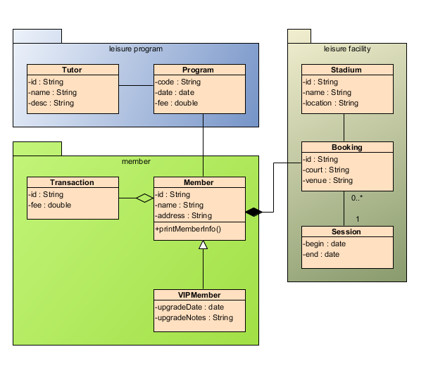
To understand these concepts in practice, let’s examine a diagram representing a “Leisure Program” and “Leisure Facility” management system. This example demonstrates how to organize complex data using packages and relationships.
1. The Class Structure
At the heart of the diagram are Classes. In UML, a class is typically represented as a rectangle divided into three compartments:
- Name: The identifier for the class (e.g.,
Tutor,Member). - Attributes: The data stored in the class (e.g.,
-id : String,-name : String). - Methods: The operations or functions the class can perform (e.g.,
+printMemberInfo()).
Notice the use of visibility symbols:
-(Private): Accessible only within the class itself.+(Public): Accessible by any other class.
2. Organizing with Packages
The diagram uses Package elements (the folders labeled “leisure program”, “member”, and “leisure facility”) to group related classes. This technique helps manage complexity by grouping classes into logical contexts. For instance, the leisure program package groups the business logic for tutors and programs, while the leisure facility package handles physical locations.
Understanding Relationships (Associations)
Classes rarely exist in isolation. They relate to one another through various types of associations. The diagram illustrates several critical relationship types:
Generalization (Inheritance)
In the member package, you will see a solid line with an empty triangle arrowhead pointing from VIPMember to Member. This represents Generalization.
This signifies an “Is-A” relationship. A VIPMember is a Member, but with additional capabilities or data (such as upgradeDate). This allows developers to reuse code defined in the parent class.
Composition (Strong Aggregation)
Observe the line connecting Member and Booking featuring a solid black diamond at the Member end. This is Composition.
Composition represents a strong “Part-Of” relationship. In this scenario, a Booking belongs exclusively to a Member. If the Member is removed from the system, the Booking loses its meaning and is typically deleted with it. This is stronger than a simple association.
Aggregation (Weak Aggregation)
Between Member and Transaction, there is a line with a hollow diamond. This represents Aggregation.
Aggregation implies a “Has-A” relationship where the lifecycle of the parts is independent. A Transaction is associated with a Member, but the Transaction could theoretically exist even if that specific Member record is deleted (e.g., in an audit log). The hollow diamond indicates a weaker ownership than the solid diamond of composition.
Cardinality (Multiplicity)
Look at the line between Booking and Session. The notation 0.. (zero to many) and 1 indicates Cardinality.
- 0..: A single
Bookingcan involve zero or manySessionrecords. - 1: A single
Sessionmust be part of exactly oneBooking.
Advanced Modeling Concepts
Beyond basic structure, Class Diagrams allow for sophisticated modeling:
Abstraction and Interfaces
While not explicitly shown in this specific image, Class Diagrams often use <<Interface>> or <<Abstract>> notations to define contracts that other classes must implement. This is crucial for creating flexible, decoupled systems.
ORM and Persistence
Modern modeling tools often extend UML to include Object-Relational Mapping (ORM) stereotypes. You might see classes marked as <<Entity Bean>> or <<ORM-Persistable>>. These tags indicate that the class is designed to be stored in a database, bridging the gap between object-oriented code and relational data.
Conclusion
The Class Diagram is more than just a drawing; it is the architectural blueprint of your software. By effectively using packages to organize code, generalization to manage hierarchy, and aggregation/composition to define ownership, you can create a model that is both robust and maintainable.
As you progress in your technical journey, remember that a good Class Diagram provides a “wide variety of usages,” serving as the foundation for everything from domain-specific data structures to detailed design patterns.
Related posts:
 Mastering System Design: A Deep Dive into the Inspection Management System Use Case Diagram
 From Chaos to Clarity: Mastering Complex BPMN Workflows with Visual Paradigm
 Mastering Minimalist Class Diagrams in Visual Paradigm
 Mastering UML Relationships: Association, Aggregation, and Composition Explained