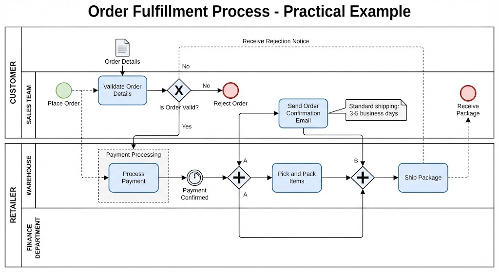
In the world of enterprise architecture and business analysis, clarity is currency. A complex workflow often gets lost in a sea of jargon, but Business Process Model and Notation (BPMN) bridges the gap between abstract strategy and technical execution. This tutorial dissects a real-world scenario: the Order Fulfillment Process. We will explore how a diagram like the one presented serves as a blueprint for an online retailer, breaking down the interaction between the Customer and the Retailer’s internal departments.
Understanding the Architecture: Pools and Lanes
The foundation of this process model is the Pool, which represents a distinct participant or organization. In this architecture, we see two primary pools defining the boundaries of the transaction:
- Customer Pool: The external actor initiating the transaction.
- Retailer Pool: The internal organization responsible for fulfilling the request.
Inside the Retailer Pool, the process is further decomposed into Lanes. These lanes act as organizational swimlanes, assigning responsibility to specific teams:
- Sales Team: Handles customer interaction, validation, and communication.
- Finance Department: Manages the monetary aspect of the order.
- Warehouse: Manages the physical logistics of picking, packing, and shipping.
Step-by-Step Process Analysis
To truly understand the system, we must walk through the flow from the initial trigger to the final delivery.
1. Initiation and Validation
The process begins with the Customer. The flow is triggered by the Start Event labeled Place Order. A Message Flow (indicated by the dashed line with an envelope icon) carries the Order Details to the Retailer.
Once the order enters the retailer’s domain, it lands in the Sales Team lane. The first technical step is the task Validate Order Details. This task is supported by a Data Object representing the actual data being reviewed.
2. Decision Making: The Exclusive Gateway
Following validation, the process hits a critical decision point represented by a diamond with an X inside. This is an Exclusive Gateway (XOR). It asks the question: “Is Order Valid?”
- The “No” Path: If validation fails, the flow moves to the Reject Order end event. A notification is sent back to the customer via a message flow.
- The “Yes” Path: If the order is valid, the process continues to the Finance Department.
3. Financial Processing
The flow moves to the Finance Department lane. Here, the task Process Payment is executed. Note the use of a Group artifact labeled “Payment Processing.” In BPMN, groups are used to visually cluster related elements for documentation purposes without affecting the process logic.
Upon completion, an Intermediate Catch Event labeled Payment Confirmed (represented by a double circle) waits for the confirmation signal before the process can proceed.
4. Parallel Execution: The Parallel Gateway
Once payment is confirmed, the process encounters a diamond with a + sign. This is a Parallel Gateway (AND). This is a crucial architectural pattern that allows the system to optimize efficiency by executing multiple tasks simultaneously.
The flow splits into two concurrent paths:
- Path A (Warehouse): The system triggers the Pick and Pack Items task. The warehouse team begins preparing the physical goods.
- Path B (Sales): Simultaneously, the Send Order Confirmation Email task is executed. The customer is notified that their order is being processed.
A Text Annotation attached to the email task clarifies the Service Level Agreement (SLA): “Standard shipping: 3-5 business days.”
5. Synchronization and Delivery
After the parallel tasks are initiated, the flow must converge. The diagram shows the paths merging at a second Parallel Gateway. In BPMN, this implies that the process flow waits for the parallel branches to synchronize before proceeding. (Note: In some variations, the “Ship Package” task itself might be the synchronization point, or the shipping event might trigger the final merge).
The flow continues to the Ship Package task in the Warehouse lane. Finally, a Message Flow indicates the package leaving the retailer’s control and arriving at the Receive Package end event in the Customer pool.
Technical Artifacts and Diagram Elements
Effective modeling relies on a rich vocabulary of symbols. Here is a breakdown of the key artifacts visible in this architecture:
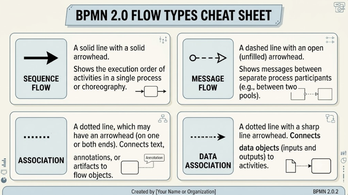
- Sequence Flow: The solid lines connecting tasks within the same pool. They define the order of execution.
- Message Flow: The dashed lines connecting different pools. They represent communication across organizational boundaries.
- Gateways: The diamonds that control flow divergence (splitting) and convergence (merging). The XOR (exclusive) ensures only one path is taken, while the AND (parallel) ensures multiple paths are taken.
- Data Objects: The icon resembling a document represents the information (Order Details) being manipulated.
Conclusion
This diagram is more than just a picture; it is a precise specification of a business logic. By utilizing BPMN, organizations can visualize bottlenecks (such as the synchronization required after payment), clarify roles (Sales vs. Warehouse), and establish clear communication channels with customers. Whether you are a business analyst defining requirements or a developer building the backend logic, this visual language ensures everyone is aligned on the Order Fulfillment architecture.