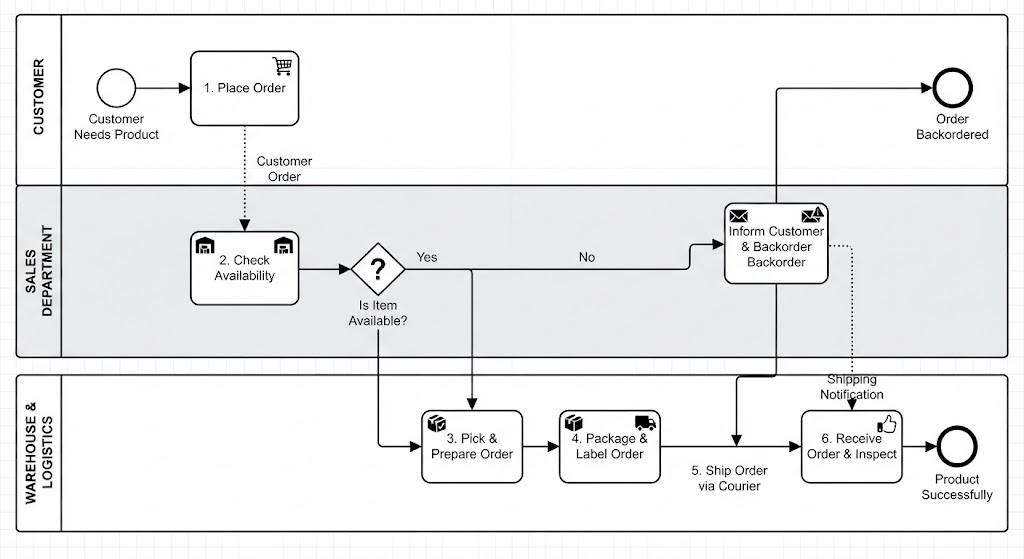
In the world of business process management, clarity is currency. This tutorial breaks down a complex Order Fulfillment workflow, demonstrating how to translate a linear narrative into a robust BPMN 2.0 diagram. We will explore the architecture of a Swimlane Diagram (or Collaboration Diagram), where different organizational units—Customer, Sales, and Warehouse—interact to achieve a shared goal.
The Architecture of the Diagram
The visual structure you see here is built on the concept of Swimlanes. This architectural pattern is crucial for defining “Who does What?” In this specific model, we see three distinct horizontal lanes representing the stakeholders:
- Customer: The initiator of the process and the ultimate recipient of the value.
- Sales Department: The control layer that validates inventory and manages exceptions.
- Warehouse & Logistics: The execution layer responsible for the physical movement of goods.
By separating these lanes, the diagram eliminates ambiguity about responsibility. If a delay occurs, you can immediately identify which lane is the bottleneck.
Step-by-Step Process Flow
1. The Initiation (Customer Lane)
The process begins with a Start Event (the white circle). This represents the trigger: Customer Needs Product. The flow moves immediately to the first activity, Place Order. Note the dashed line connecting “Place Order” to the Sales lane. This is a Message Flow (dotted line with an open arrow), indicating an asynchronous communication. The customer does not wait in the system; they send a signal, and the Sales Department picks it up asynchronously.
2. The Decision Gate (Sales Department)
The Sales Department receives the order and performs the activity Check Availability. Following this task is a Exclusive Gateway (the diamond shape with a question mark). This is the pivotal logic point of the system.
The diamond splits the path into two mutually exclusive outcomes:
- Yes (Available): The path continues downward to the Warehouse.
- No (Not Available): The path leads to an exception handler: Inform Customer & Backorder Backorder.
Technical Note: The diamond represents an XOR gateway. It ensures that the process cannot branch into both paths simultaneously. If the item is not available, the process must handle the backorder scenario before ending.
3. The Execution Pipeline (Warehouse Lane)
Once the item is confirmed, the message flows to the Warehouse lane. Here, the process is strictly sequential:
- Pick & Prepare Order: Retrieving the physical stock.
- Package & Label Order: Securing the item and preparing it for transport.
- Receive Order & Inspect: The final validation step before hand-off.
Notice the Intermediate Message Event (envelope icon) between the Sales and Warehouse lanes. This represents the Shipping Notification. This is a critical piece of architecture: it shows that the Sales Department is notified of the status change, keeping the stakeholders synchronized.
4. Termination
The diagram features two distinct End Events (the thick black circles):
- Order Backordered: An abnormal end state resulting from the “No” decision in the Sales lane.
- Product Successfully: The happy path end state, achieved only after the final inspection in the Warehouse.
Visual Modeling Syntax
To recreate this architecture in a tool like Visual Paradigm or to understand the underlying XML schema, you must map these visual elements to their BPMN definitions:
<!-- Swimlane Definition (Pool & Lanes) -->
<pool id="OrderProcess" name="Order Fulfillment">
    <lane id="Customer" name="Customer"/>
    <lane id="Sales" name="Sales Department"/>
    <lane id="Warehouse" name="Warehouse & Logistics"/>
</pool>

<!-- Flow Example: Customer to Sales (Message Flow) -->
<messageFlow id="M_Flow1" sourceRef="PlaceOrder" targetRef="CheckAvailability"/>

<!-- Flow Example: Sales to Warehouse (Sequence Flow) -->
<sequenceFlow id="S_Flow1" sourceRef="CheckAvailability" targetRef="PickPrepareOrder"/>

<!-- Logic Example: Exclusive Gateway (XOR) -->
<gateway id="G_AvailabilityCheck" type="Exclusive"/>
<sequenceFlow id="S_Flow_Yes" sourceRef="G_AvailabilityCheck" targetRef="PickPrepareOrder"/>
<sequenceFlow id="S_Flow_No" sourceRef="G_AvailabilityCheck" targetRef="InformCustomer"/>
Why This Matters
Visualizing this process is not just about drawing boxes; it is about defining the System Architecture. By separating the logical decision-making (Sales) from the physical execution (Warehouse), the diagram allows developers to map these steps to different microservices or legacy systems. It ensures that the “Backorder” exception is never lost in the noise of the happy path.