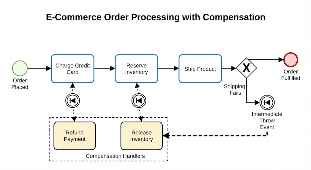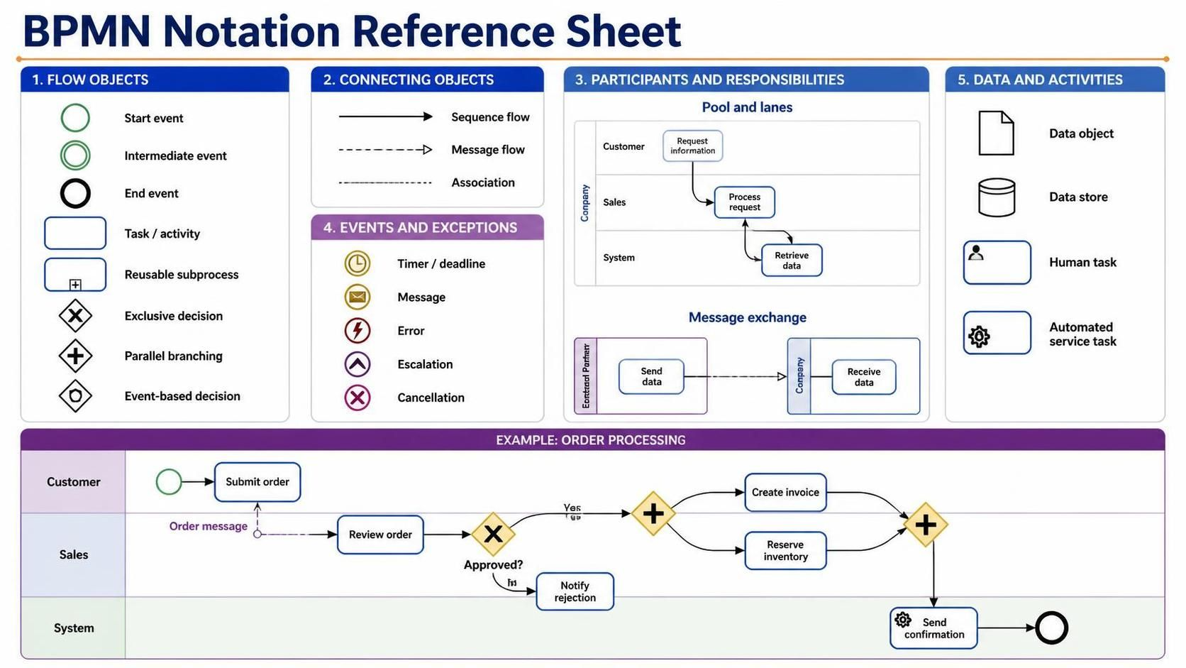
Welcome to this technical tutorial on Business Process Model and Notation (BPMN). As we transition from conceptual discussions to practical implementation, it is crucial to understand that BPMN is not merely a drawing tool; it is a standardized language for business operations. This guide will deconstruct the architecture of a BPMN model, analyzing the specific components shown in our reference sheet and demonstrating how to structure complex workflows like the Order Processing scenario.
1. The Core Architecture: Flow Objects
At the heart of any BPMN diagram are Flow Objects. These are the building blocks that define the “heartbeat” of your process. As seen in the top-left quadrant of our reference, the architecture relies on three distinct types of events and a specific type of activity.
- Events: Represented by circles.
- Start Event: The trigger. A thin green circle indicates where the process begins.
- Intermediate Event: A thick green circle. This represents something happening during the process, such as waiting for a timer or receiving a message.
- End Event: The termination point. A thick black circle indicates the successful completion of the workflow.
- Activities (Tasks): Represented by rounded rectangles. This is where the work happens. In the “Order Processing” example, tasks like “Submit order” and “Review order” are the execution points.
- Gateways: Represented by diamonds. These control the branching logic. The “X” inside the diamond (Exclusive Gateway) acts as a decision point, forcing the flow to take only one path based on a condition (e.g., “Approved?”).
2. Connecting Objects: The Nervous System
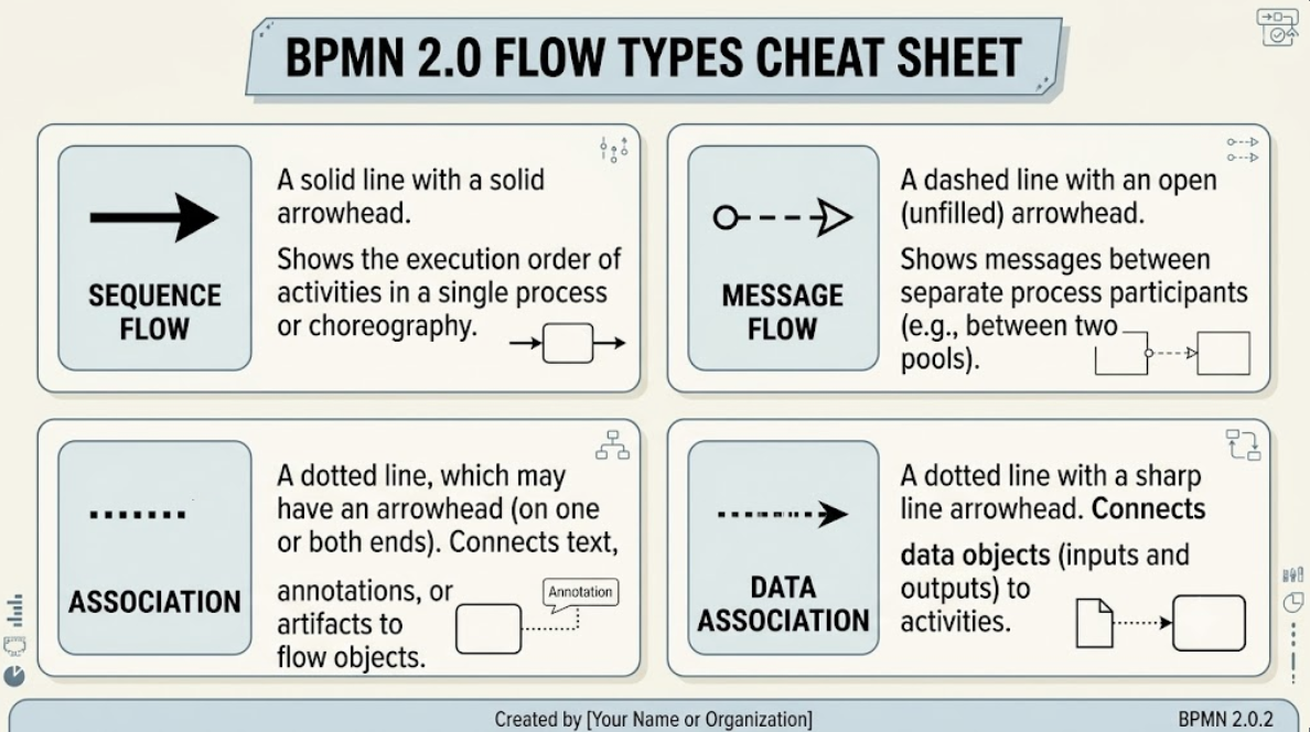
Once the flow objects are defined, they must be linked. The reference sheet highlights three critical connecting objects that define the logic of the model:
- Sequence Flow: The solid black arrow. This defines the order of activities within a single process. It answers the question: “What happens next?”
- Message Flow: The dashed arrow. This is vital for multi-party interactions. In our example, the “Order message” is sent from the Customer to the Sales department. This is distinct from sequence flow because it crosses organizational boundaries (swimlanes).
- Association: The dotted line. This connects data objects or annotations to specific flow objects, providing context without interrupting the flow.
Pro Tip: The Message Flow Rule
When designing complex systems, remember that Message Flows must never cross a boundary without a source and a target event. You cannot simply have a dashed line floating in mid-air. It must originate from a Send Task or Message Start Event and terminate at a Receive Task or Message Intermediate Event.
3. Participants and Responsibilities: Swimlanes
A process is rarely a solo act. The “Pool and Lanes” section of the reference sheet illustrates how to visualize responsibility. A Pool represents a participant (like a Company), and Lanes represent the internal subdivisions (like Sales, Customer, or System).
This structure is critical for the “Order Processing” diagram. By separating the Customer, Sales, and System into different lanes, we clearly see:
- Handoffs: The moment the “Order message” crosses from the Customer lane to the Sales lane, a handoff occurs.
- System Automation: The “Send confirmation” task resides in the System lane, indicating that no human is required for this specific step—it is an automated service.
4. Advanced Logic: Events and Exceptions
Real-world business processes are messy. They involve errors, escalations, and external interruptions. The reference sheet details how BPMN handles these scenarios:
- Timers: The clock icon allows you to model time-based triggers (e.g., “Wait 24 hours before escalation”).
- Escalations: The upward arrow icon signifies a breach of service level agreements (SLAs) or a need to notify management.
- Cancellations: The red “X” icon allows you to stop a specific activity or the entire process instance.
5. Data and Activities
Finally, the “Data and Activities” section of the reference sheet distinguishes between human effort and system logic. Notice the Human Task icon (person silhouette) versus the Automated Service Task icon (gear). This distinction is vital for tooling selection. If you are using a tool like Visual Paradigm, you can map the Human Task to a specific user role in your LDAP directory, while the Automated Service Task can be mapped to a specific API endpoint.
Tooling: Visual Paradigm BPMN
While understanding the theory is essential, the true power of BPMN lies in its implementation. For teams looking to move from static diagrams to dynamic, executable models, Visual Paradigm serves as a cornerstone tool.
Visual Paradigm BPMN is not just a diagramming tool; it is an integrated modeling environment. It seamlessly integrates with the architectural pillars discussed above to boost team collaboration and productivity in the following ways:
- Unified Modeling Environment: Unlike basic drawing tools, Visual Paradigm allows you to model the BPMN process and then instantly link it to database schemas or code classes. This bridges the gap between the “Sales” process and the actual “System” implementation.
- Collaborative Workflow: The platform supports multi-user editing and version control. When the “Sales” team modifies the “Review order” gateway, the “System” team is immediately alerted to the change, ensuring that the API contracts remain valid.
- Usage Cases:
- Legacy Migration: Use Visual Paradigm to import existing flowcharts and automatically convert them into standard BPMN 2.0 compliant models.
- Process Simulation: Before implementing the “Order Processing” logic, run a simulation to see if the “Exclusive Gateway” (Approved?) creates a bottleneck in the system.
Conclusion
By mastering the flow objects, connecting objects, and swimlanes outlined in this reference sheet, you gain the ability to design robust, executable business processes. Whether you are modeling a simple approval chain or a complex multi-party transaction, the standardization of BPMN ensures that your diagrams are universally understood.