


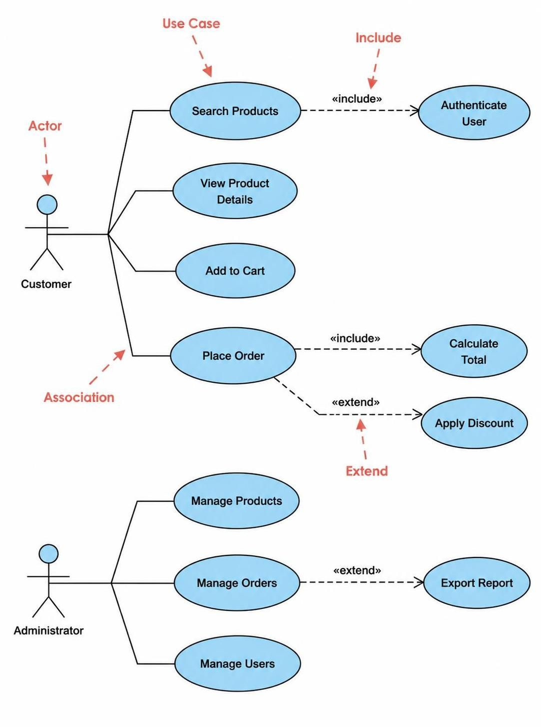
In the realm of software engineering, capturing requirements is just as critical as writing the code itself. When you need to visualize the dynamic behavior of a system—how it responds to users and external events—Use Case Diagrams are the industry standard. These diagrams provide a high-level map of functionality, ensuring that developers and stakeholders are aligned on what the system must do before a single line of code is written.
This tutorial breaks down the anatomy of a Use Case Diagram, focusing on the relationships that drive system logic, using a classic Online Shopping System as our example.
1. The Core Components
Before diving into the logic, we must define the building blocks visible in our system architecture.
The Actor
An Actor represents a user or an external system that interacts with your application. They are depicted as stick figures and are categorized based on their role:
- Customer: The primary end-user browsing and purchasing items.
- Administrator: The internal user managing inventory, orders, and system users.
The Use Case
A Use Case represents a specific functional requirement or a goal the actor wants to achieve. In the diagram, these are the ovals. Examples include:
- Browse Products: A simple read-only action.
- Place Order: A complex workflow involving multiple steps.
- Manage Users: An administrative function.
2. Decoding the Relationships
The true power of a Use Case Diagram lies in the lines connecting actors to use cases and use cases to other use cases. These lines define the flow of control.
Association (The Connection)
As seen in the diagram, a solid line connects the Customer to Search Products and Add to Cart. This is an Association. It simply indicates that the actor initiates or participates in this specific use case.
Include (Mandatory Dependency)
The «include» relationship represents a mandatory link. It means that the base use case cannot be completed without the included use case happening first.
- Example: Look at Search Products. It has a dashed arrow pointing to Authenticate User. This implies that before a guest can even search for products, the system must verify their identity. It is a non-optional dependency.
- Another Example: The Place Order use case includes Calculate Total. You cannot place an order without calculating the final price.
Extend (Optional Behavior)
The «extend» relationship represents optional or conditional behavior. It adds functionality to the base use case only under specific circumstances.
- Example: The diagram shows Apply Discount extending Place Order. This means the customer can place an order, but if they have a coupon code, the “Apply Discount” functionality is triggered. If no code is entered, this path is skipped.
- Example: Export Report extends Manage Orders. The admin manages orders, but exporting a report is an extra feature available only when needed.
3. Visualizing the Logic
Let’s look at how these components form a coherent workflow for our Customer. The logic flows as follows:
1. Customer selects "Search Products".
2. System triggers «include»: Authenticate User.
3. Upon success, Customer can "View Product Details" or "Add to Cart".
4. Customer selects "Place Order".
5. System triggers «include»: Calculate Total.
6. System checks for condition: Does customer have a discount?
7. IF YES -> Trigger «extend»: Apply Discount.
8. Finalize Order.4. Tooling and Collaboration
While sketching on a whiteboard is great for brainstorming, translating these concepts into a maintainable system architecture requires robust tooling. This is where Visual Paradigm shines as a comprehensive modeling solution.
Seamless Integration for Teams
Visual Paradigm (VP) is not just a diagramming tool; it is a full lifecycle platform. By integrating UML modeling directly with development workflows, it bridges the gap between design and implementation.
- Collaborative Design: Teams can work on the same Use Case Diagram simultaneously. Changes are synchronized, ensuring that the “Customer” role defined by one developer is recognized by the database architect.
- Code Generation: VP can reverse engineer existing code to create Use Case Diagrams or forward engineer diagrams into skeleton code (e.g., Java or C#), drastically reducing boilerplate development time.
- Requirement Management: The tool allows you to link specific use cases to detailed requirement documents, ensuring that no functionality is lost during the development phase.
By adopting a tool like Visual Paradigm, you move from static diagrams to a dynamic system model that evolves with your product, ensuring that the “Place Order” logic remains consistent from the design phase all the way to the deployed application.
Related posts:
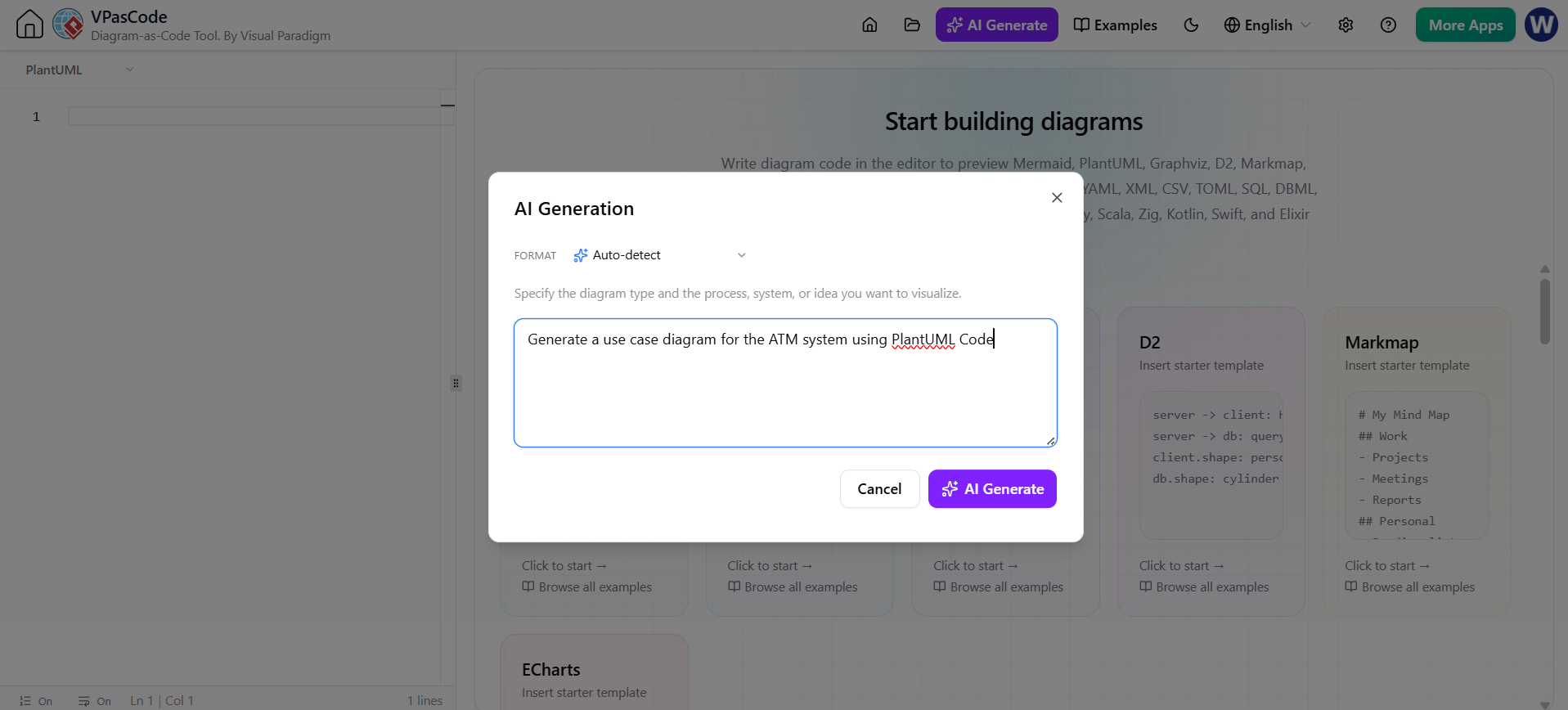 Revolutionizing System Modeling: The Power of Instant AI Diagram Generation
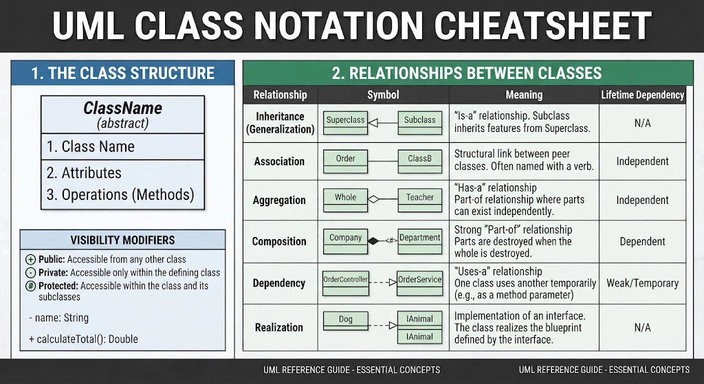 Mastering UML Class Diagrams: A Comprehensive Guide to Structure and Relationships
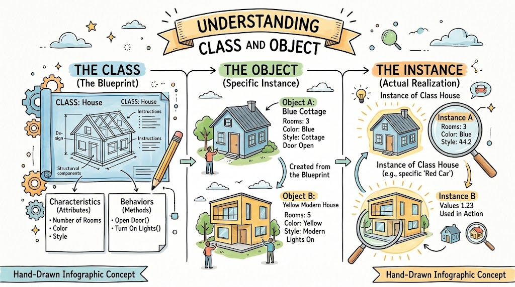 Mastering Object-Oriented Architecture: A Deep Dive into Classes, Objects, and Instances
 Mastering UML Associations: Navigability, Multiplicities, and Association Classes