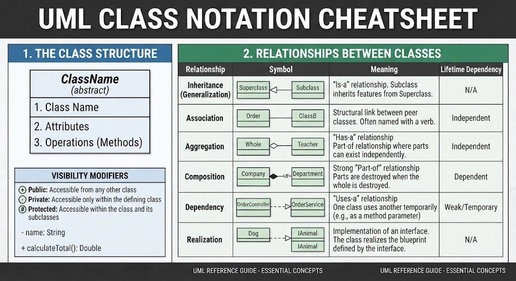
In the world of software engineering, communication is key. Before a single line of code is written, architects and developers must agree on the system’s design. Unified Modeling Language (UML) serves as the universal blueprint for this process. Among its various diagram types, the Class Diagram is arguably the most critical for defining the static structure of an application.
This tutorial breaks down the two fundamental pillars of UML class modeling: the internal anatomy of a class and the complex web of relationships that connect them. By the end of this guide, you will be able to read and construct class diagrams with confidence.
1. The Anatomy of a Class
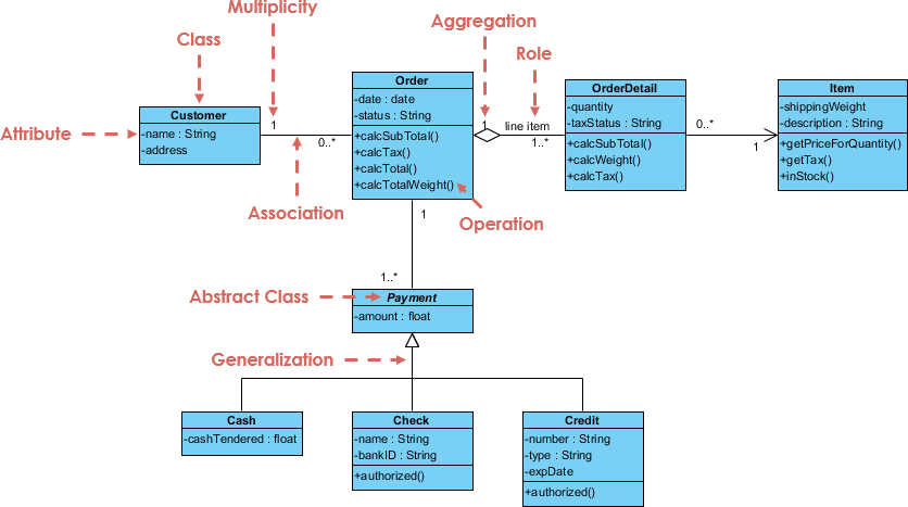
At its core, a UML class is a blueprint for objects. It represents a category of things that share the same structure, behavior, and semantics. Visually, a class is represented by a rectangle divided into three distinct horizontal partitions. Understanding what goes into each section is the first step in effective modeling.
Partition 1: The Class Name
The top section is reserved for the Class Name. This is the identifier used throughout the software to reference the type. A crucial detail in UML notation is the handling of abstract classes. If a class is marked as abstract (meaning it cannot be instantiated on its own), its name is written in italics.
Partition 2: Attributes (State)
The middle partition lists the Attributes. These represent the data or state of the class. In object-oriented programming, these are often synonymous with member variables or properties. Each attribute typically follows a specific format:
- Name: The identifier (e.g.,
name). - Type: The data type (e.g.,
String).
For example, a Student class might have an attribute id: Integer.
Partition 3: Operations (Behaviors)
The bottom partition defines the Operations or Methods. These are the behaviors the class can perform or the services it provides to the rest of the system. A method signature usually includes the name, input parameters (if any), and a return type.
Consider a Calculator class. It might define an operation like calculateTotal(): Double, indicating that it performs a calculation and returns a Double value.
Visibility Modifiers
Before diving into relationships, we must understand how to control access to these attributes and methods. UML uses specific symbols to denote visibility, which map directly to access control in programming languages:
+(Public): Accessible from any other class. This is the most open level of access.-(Private): Accessible only within the defining class itself. This encapsulates data.#(Protected): Accessible within the class and its subclasses. This allows for inheritance-based access.
2. Relationships Between Classes
Classes rarely exist in isolation. They interact to form a cohesive system. UML defines several specific ways classes can interact, and understanding the semantic difference between these relationships is vital for accurate modeling. The lines connecting the classes tell a story about how the objects relate to one another.
Inheritance (Generalization)
The Generalization relationship represents an “Is-a” relationship. This is the mechanism of inheritance. If you have a Subclass and a Superclass, and the subclass inherits features from the superclass, you use a solid line with a hollow arrowhead pointing to the superclass.
- Symbol: Solid line with a hollow triangle arrowhead.
- Meaning: The subclass is a specialized version of the superclass (e.g., a
Car“Is-a”Vehicle).
Association
An Association is a structural link between peer classes. It implies that objects of one class have a reference to objects of another class. This is often the most basic relationship, frequently named with a verb to describe the interaction.
- Symbol: Simple solid line.
- Meaning: A structural link where the classes are peers (e.g., a
Teacheris associated with aStudent). - Lifetime: Independent. One object does not strictly dictate the existence of the other.
Aggregation
Aggregation is a specialized form of association that represents a “Has-a” relationship. It describes a part-whole relationship where the parts can exist independently of the whole. Think of it as a weak containment.
- Symbol: Solid line with an unfilled (white) diamond at the “whole” end.
- Example: A
Universityhas manyDepartments, but if the University closes, the Departments might still exist as separate entities. - Lifetime: Independent.
Composition
Composition is the strongest form of association. It represents a strong “Part-of” relationship. Unlike aggregation, the lifecycle of the part is strictly tied to the whole. If the “whole” is destroyed, the “part” is destroyed with it.
- Symbol: Solid line with a filled (black) diamond at the “whole” end.
- Example: A
Companyis composed ofEmployees. If the Company dissolves, the employment relationship ends, and the internal structure of that specific company instance is destroyed. - Lifetime: Dependent.
Dependency
A Dependency represents a usage relationship. It is a weaker link than association, often used to describe a temporary relationship. One class uses another temporarily, such as passing it as a method parameter or using it within a specific method.
- Symbol: Dashed line with an open arrowhead pointing to the used class.
- Example: A
ReportGeneratordepends on aDataParser. The generator uses the parser to function, but they are not structurally linked permanently. - Lifetime: Weak or Temporary.
Realization
Finally, Realization is the relationship between a class and an interface. It signifies that the class implements the blueprint defined by the interface. It is essentially the implementation of an abstract contract.
- Symbol: Dashed line with a hollow arrowhead pointing to the interface.
- Meaning: The class realizes the interface (e.g., a
Dogclass realizes theAnimalinterface).
Conclusion
UML Class Diagrams provide a powerful way to visualize the architecture of a software system. By mastering the Class Structure (Attributes, Operations, and Visibility) and the Relationships (Inheritance, Association, Aggregation, Composition, Dependency, and Realization), you gain the ability to design robust, scalable, and maintainable software systems.