


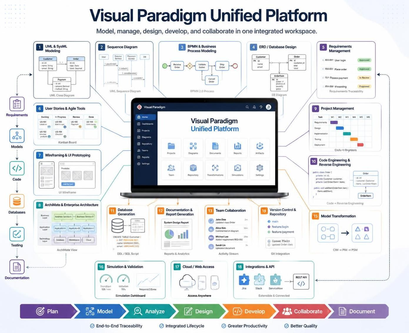
In the rapidly evolving landscape of software engineering, the disconnect between business stakeholders and development teams often leads to project failure. The Visual Paradigm Unified Platform addresses this challenge by offering an integrated workspace that bridges the gap between abstract business analysis and concrete software implementation. This tutorial explores how the platform functions as a central hub for the entire software development lifecycle (SDLC), ensuring that every line of code traces back to a specific business requirement.
The Core Architecture: A Unified Ecosystem
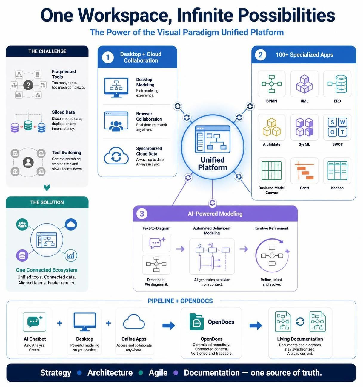
Unlike traditional toolchains where a business analyst uses one tool (like Excel or Visio) and a developer uses another (like Eclipse or IntelliJ), the Unified Platform operates on a single data model. This architecture supports a “Model-Driven Architecture” (MDA) approach, where models are not just static documentation but living artifacts that drive the development process.
The platform integrates several critical pillars:
- Visual Modeling: The foundation, using UML and SysML to represent system behavior.
- Business Analysis: Capturing requirements and processes before a single line of code is written.
- Agile & Project Management: Managing the workflow of user stories and sprints.
- Code & Database Engineering: Automating the generation of source code and database schemas from models.
- Collaboration: Real-time team coordination within a shared cloud repository.
Connecting the Dots: Traceability
The most powerful feature of this architecture is End-to-End Traceability. When a business stakeholder defines a requirement (e.g., “User must be able to place an order”), the system allows you to link that requirement directly to a BPMN process, a UML class diagram, a user story, and finally, the Java or C# code that implements it. If the requirement changes, the impact analysis tool can instantly identify which parts of the codebase are affected.
Step-by-Step Workflow
1. Business Process Modeling (BPMN)
The journey begins with understanding the business logic. Using BPMN 2.0, teams map out the “Happy Path” and exception handling. For example, a “Receive Order” process might trigger a sequence of events: validating the customer, checking stock, and initiating payment.
2. System Modeling (UML & SysML)
Once the process is defined, the technical team translates these flows into system models. This involves creating:
- Class Diagrams: Defining the structure of data entities like
Customer,Order, andPayment. - Sequence Diagrams: Illustrating the interaction between objects (e.g., how the UI sends a message to the Backend Service).
3. Database Design (ERD)
With the object structure defined, the platform facilitates the design of the underlying data storage. Entity Relationship Diagrams (ERDs) allow for the normalization of data, ensuring that relationships (One-to-Many, Many-to-Many) are correctly represented before database generation.
4. Code Engineering & Reverse Engineering
The platform automates the translation of these high-level models into executable code. Through forward engineering, a Customer class in the diagram becomes a class Customer in Java. Conversely, reverse engineering allows developers to import existing legacy code, visualize it as a UML diagram, and understand the architecture without reading the source code line-by-line.
Tooling: The Core Pillars of the Visual Paradigm Ecosystem
The ecosystem is designed to support specific roles within a development team, ensuring that every professional has the right tools for their specific task while remaining connected to the central project.
Visual Modeling & Architecture
At the heart of the system is the modeling engine. It supports a wide array of standards including UML (Unified Modeling Language) for software design, SysML for systems engineering, and ArchiMate for enterprise architecture. This allows architects to model the business layer, application layer, and technology layer simultaneously.
Business Analysis & Agile Management
The platform integrates requirements management directly with project management tools. Teams can create User Story Maps and Backlogs (Kanban boards) that are linked to the actual requirements. This ensures that the team is always working on the highest priority items, and the “Done” status in the Kanban board can automatically update the requirement status.
Database & Code Engineering
For the technical implementers, the ecosystem provides robust database tools. It supports DDL (Data Definition Language) scripts for generating tables, views, and stored procedures. It also supports round-trip engineering, meaning changes made in the code (like adding a new field to a class) can be pushed back up to the model, keeping the documentation up to date automatically.
Collaboration & Cloud Integration
The Unified Platform eliminates the need for file sharing. Through VP Online and the cloud-based applications, team members can access the shared workspace. Features include version management, conflict resolution, and task coordination, allowing geographically distributed teams to work on the same project in real-time.
Simulation & Validation
Before deployment, the platform allows for simulation. By running the models, teams can validate the logic. For example, a simulation of a BPMN process can reveal bottlenecks or deadlocks before the application is even built. This “Shift Left” testing approach significantly reduces the cost of fixing bugs.
Conclusion
The Visual Paradigm Unified Platform is more than just a drawing tool; it is a comprehensive lifecycle management system. By unifying the disparate needs of analysts, architects, developers, and testers, it ensures that the final software product aligns perfectly with the original business vision.
Related posts:
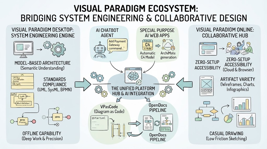 Mastering the Visual Paradigm Ecosystem: Bridging System Engineering & Collaborative Design
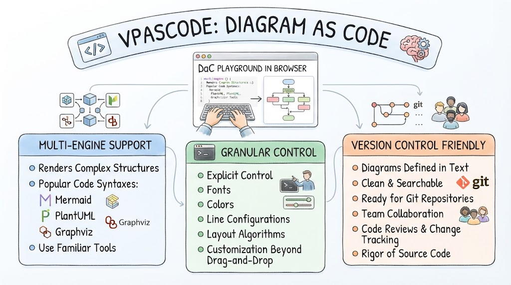 Mastering Diagram as Code: An Architectural Guide to VPasCode
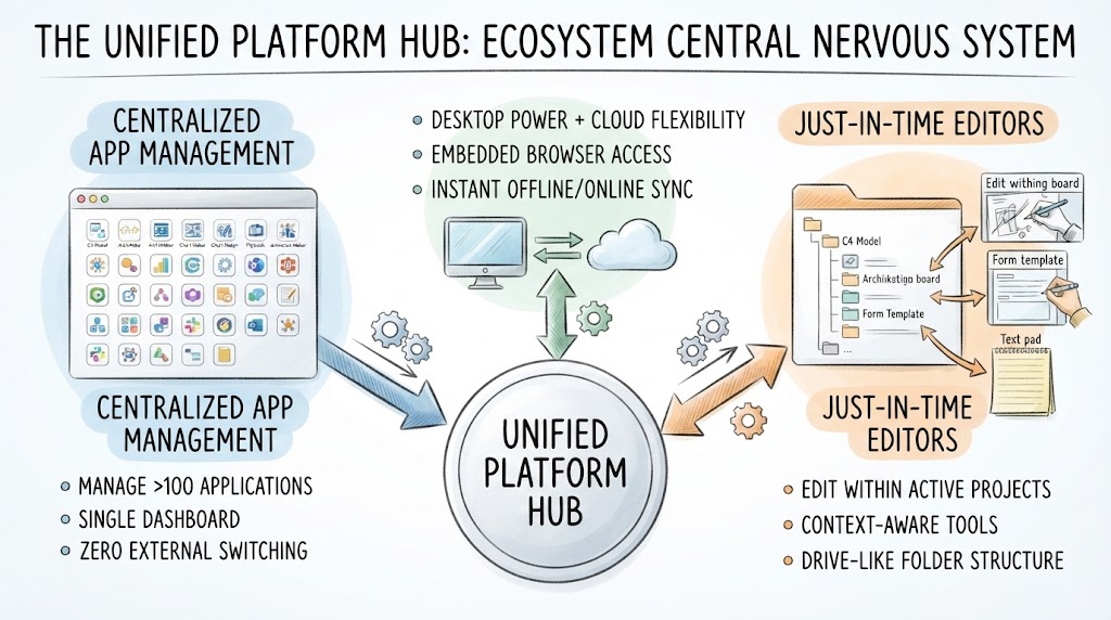 Mastering the Unified Platform Hub: A Guide to Ecosystem Architecture and Workflow Integration
 Mastering the Visual Paradigm Unified Platform: From VPasCode to Living Documentation