Test

Payment Authorization Sequence Diagram VPasCode

Payment Authorization Sequence Diagram VPasCode

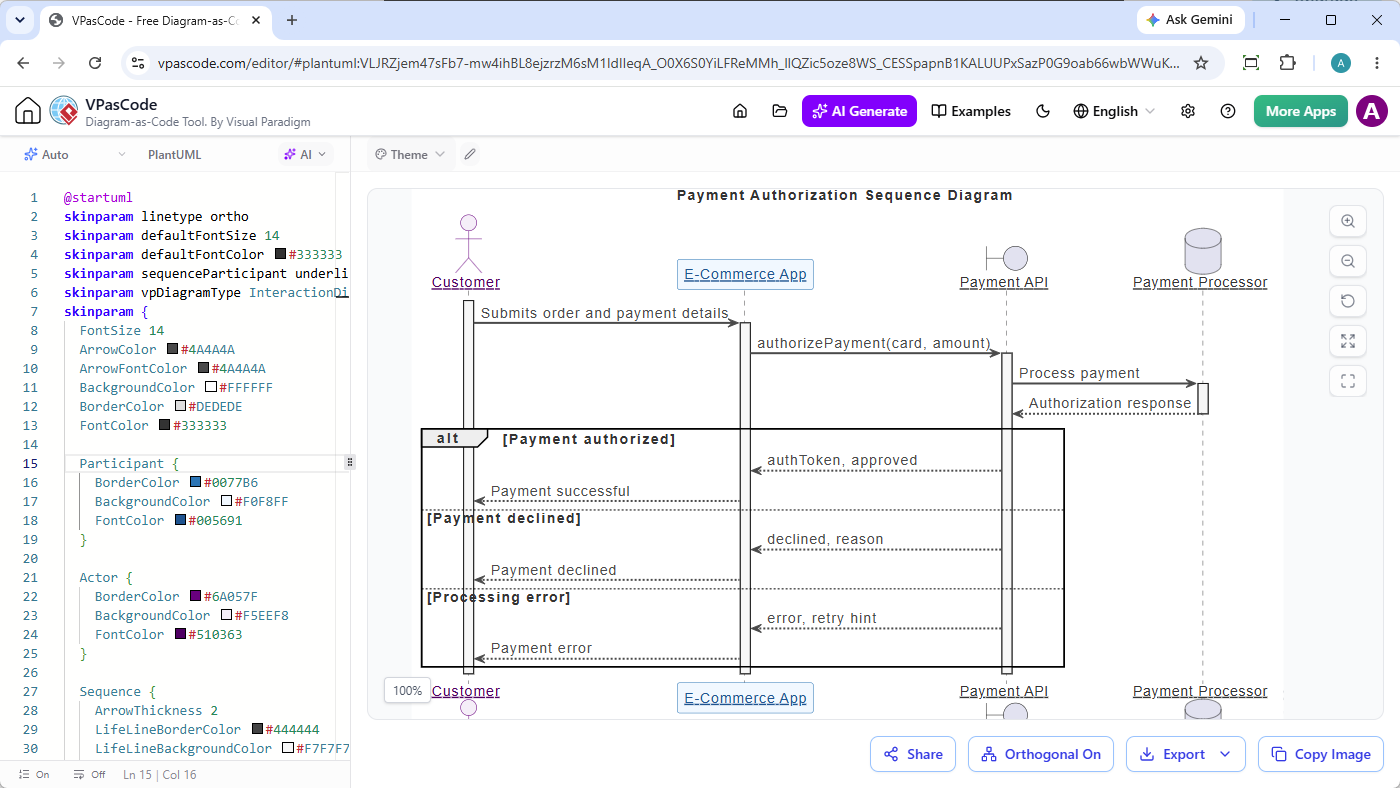
The image displays a “Payment Authorization Sequence Diagram” rendered in the VPasCode editor interface, illustrating the interaction flow between a Customer, E-Commerce App, Payment API, and Payment Processor. The diagram visualizes the authorization process with messages for submitting details, processing payments, and handling conditional outcomes like success, decline, or processing errors.

Free vs Premium AI Diagrams

Free vs Premium AI Diagrams

The image displays a comparison between free and premium AI tools for generating and editing diagrams using plain text prompts, highlighting features like sequence diagram generation for payment APIs and safe refactoring.

ATM Use Case Diagram

ATM Use Case Diagram

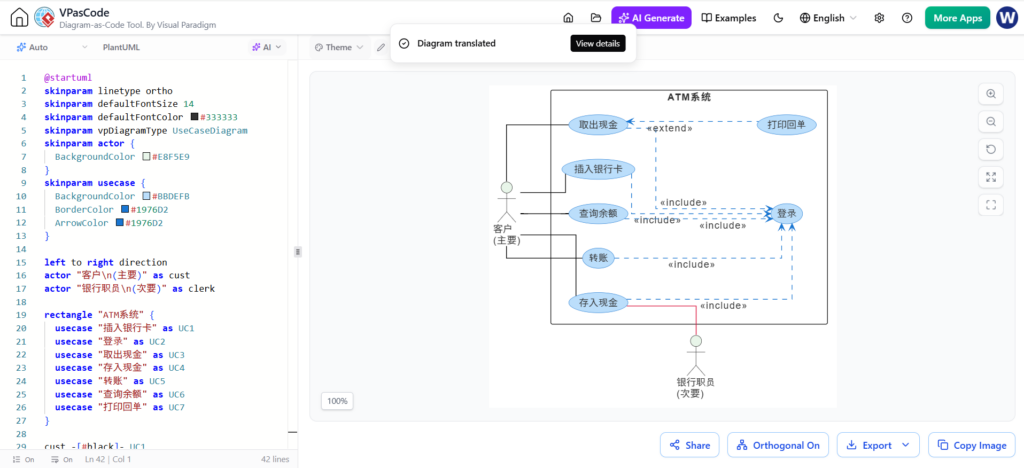
The diagram titled ATM系统 displays a UML use case diagram detailing interactions between actors, including customers and bank staff, and various ATM functions like cash withdrawal, balance inquiries, and card transactions. It also highlights relationships such as include and extend to show dependencies between processes like card insertion and login.

ATM System Use Case Diagram UML PlantUML

ATM System Use Case Diagram UML PlantUML

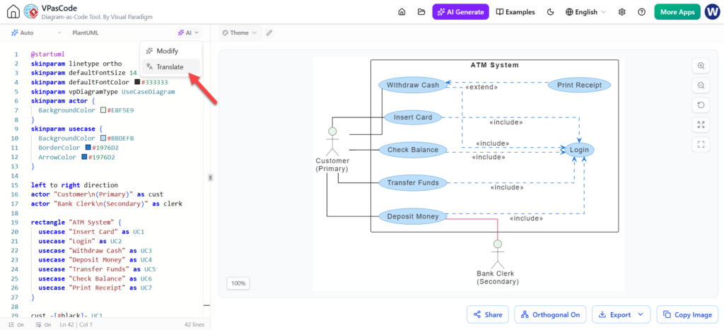
An ATM System use case diagram visualizes interactions between a Primary Customer actor and a Secondary Bank Clerk actor with system functions such as Insert Card, Withdraw Cash, and Check Balance. The diagram explicitly shows include relationships where Login is required before using specific services, along with an extend relationship for Print Receipt.

ATM Use Case Diagram with PlantUML

ATM Use Case Diagram with PlantUML

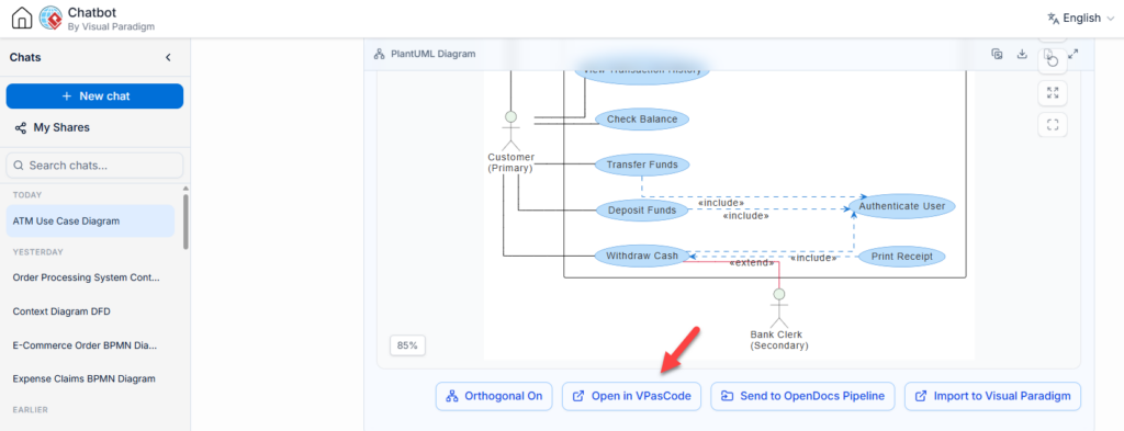
An ATM use case diagram illustrates interactions between a Primary Customer and Secondary Bank Clerk with system functions like Check Balance, Transfer Funds, Deposit Funds, Withdraw Cash, Authenticate User, and Print Receipt. A red arrow points to the “Open in VPasCode” button positioned below the diagram.

ATM Use Case Diagram

ATM System Use Case Diagram

ATM system UML Use Case diagram showing customer and bank employee actors interacting with functions like card insertion, cash withdrawal, balance inquiry, money transfer, and cash deposit. The diagram includes extend and include relationships between use cases with blue ellipses connected by arrows within a black-bordered rectangle labeled “ATM系统”.

PlantUML Class Diagram Editor

PlantUML Class Diagram Editor

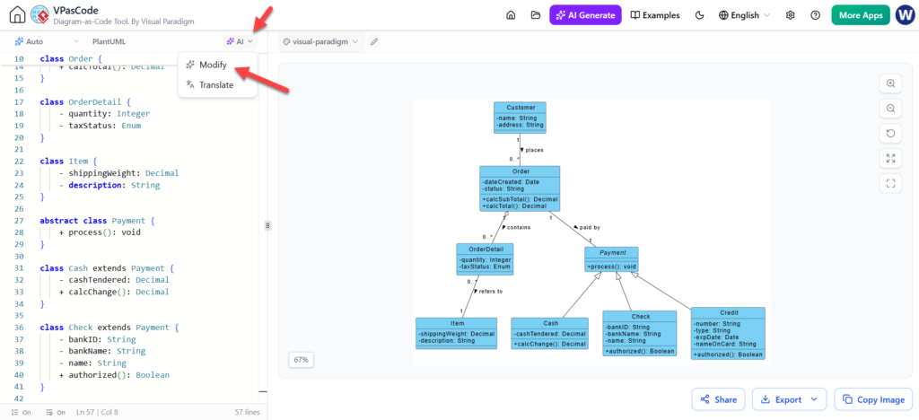
The visual paradigm tool screen features a PlantUML code editor on the left alongside a diagram displaying class and object relationships on the right. A red arrow points to an AI dropdown menu with the options “Modify” and “Translate.”

VPasCode Next-Generation Diagram-as-Code Platform Features

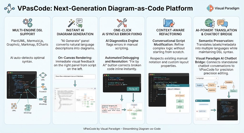
VPasCode Next-Generation Diagram-as-Code Platform Features

Native AI Integration: AI capabilities are embedded directly within the editor environment, eliminating context switching between external LLM chat interfaces and the diagramming canvas.

Multi-Engine DSL Support: The platform dynamically supports multiple Domain-Specific Languages including PlantUML, Mermaid.js, Graphviz, Markmap, and ECharts, with AI auto-detection selecting the optimal syntax for the task.

Context-Aware Refactoring: AI modifications respect existing manual notation and layout properties, allowing for iterative refinement without destroying prior work.

Semantic-Preserving Translation: Automated translation filters convert labels and metadata for international teams while strictly maintaining the underlying DSL syntax framework required for rendering.

AI Diagnostics Engine: A built-in validator that not only flags syntax errors but provides one-click, inline corrections by parsing broken logic against valid DSL grammar.

Enhanced Real-Time Collaboration Visual Paradigm

Enhanced Real-Time Collaboration Visual Paradigm

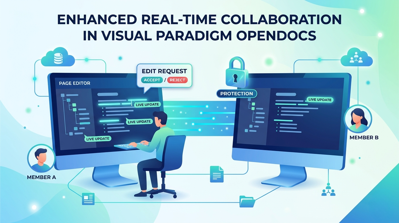
The image displays a promotional graphic for “Enhanced Real-Time Collaboration in Visual Paradigm OpenDocs.” It illustrates a workflow where “Member A” and “Member B” collaborate on a “Page Editor” interface, featuring live updates, edit request controls (accept/reject), and protection locks, all connected via cloud networks.

Video Rental Shop Level 0 Data Flow Diagram

Video Rental Shop Level 0 Data Flow Diagram

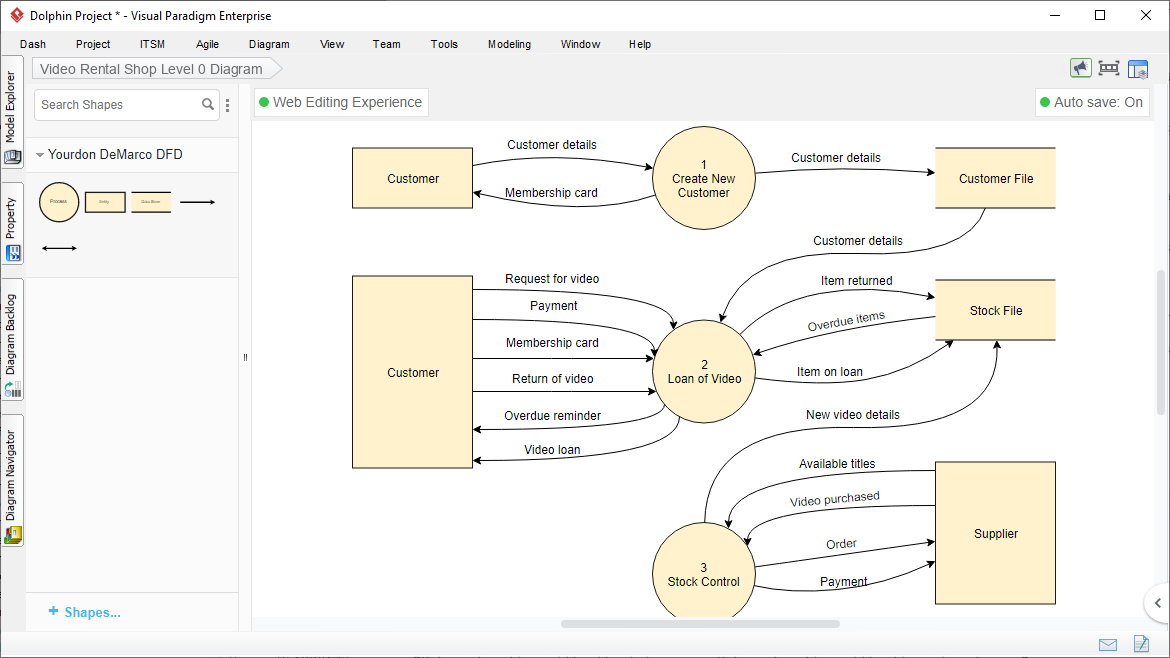
The level-0 data flow diagram (DFD) for a “Video Rental Shop” depicts the flow of data between customers, suppliers, internal processes, and data stores. The diagram includes three processes: Create New Customer, Loan of Video, and Stock Control, interconnected with entities like Customer, Supplier, Customer File, and Stock File via labeled data flows.

Scroll to Top