In the realm of Business Process Management (BPM), a diagram is merely a drawing until it adheres to a strict logic. Creating a diagram is easy; creating a clear diagram requires discipline. Based on BPMN (Business Process Model and Notation) semantics and practical experience, this tutorial breaks down the anatomy of the “Order Process” diagram shown above. We will explore how to model complex logic, distinguish between different types of flows, and ensure your process models are robust and deadlock-free.
1. The Anatomy of the Order Process: A Step-by-Step Walkthrough
Let’s dissect the diagram to understand the lifecycle of an order from the initial demand to the final payment relay. The process flows from left to right, utilizing a mix of sequence flows, gateways, and events to manage decision-making and concurrency.
The Initial Phase: Demand and Comparison
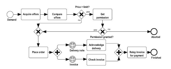
The process begins with a Start Event (the circle on the far left) labeled “Demand.” This signals that a customer request has entered the system. The process immediately moves to a task: Acquire offers, followed by Compare offers.
Phase 1: The Decision Logic (XOR Gateway)
Once offers are compared, the process encounters a diamond shape with a cross inside. This is an Exclusive Gateway (XOR). It represents a decision point where the path branches based on a condition.
- Condition: The outgoing flow labeled “yes” implies the condition Price > limit? was met. The process moves to the task Get permission.
- Condition: The outgoing flow labeled “no” implies the price is within limits. The process bypasses the permission task entirely.
Key Insight: Notice how the flow from the “no” path skips the “Get permission” task entirely, merging back into the main flow later. This is a classic example of conditional branching.
Phase 2: Permission and Synchronization
After the task Get permission (or if permission was skipped), the flow converges at a second XOR gateway. This gateway asks: Permission granted?
- If no: The flow moves to the End Event labeled “Aborted.” This is a standard termination of the process instance.
- If yes: The process proceeds to the task Place order.
Phase 3: Concurrency (Parallel Gateway)
After placing the order, the process hits a diamond with a plus sign inside. This is a Parallel Gateway. Unlike the exclusive gateway, this does not make a choice; it splits the flow into multiple paths that happen simultaneously.
Two parallel tasks are triggered:
- Acknowledge delivery (triggered by a Message Event – the envelope icon).
- Check invoice (triggered by a Message Event).
The use of Message Events (the envelope icons) indicates that these tasks are likely external interactions—receiving a delivery note and receiving an invoice from a supplier.
Phase 4: The Final Merge and Termination
Once both parallel tasks (“Acknowledge delivery” and “Check invoice”) are complete, the flow converges at a second Parallel Gateway (the plus sign). This synchronizes the parallel branches. The process will not continue until both tasks are finished.
Finally, the synchronized flow leads to the task Relay invoice for payment and concludes at the End Event labeled “Finished.”
2. Notation Deep Dive: Understanding the Symbols
To interpret BPMN diagrams effectively, you must understand the specific symbols used. Here is a breakdown of the notation found in this specific example.
Gateways: The Traffic Controllers
Gateways control the divergence and convergence of paths. The visual marker inside the diamond defines the logic:
- Exclusive Gateway (XOR) – Big X: Used for decisions. Only one path is taken.
- Usage in Diagram: Checking if “Price > limit” or if “Permission granted?”.
- Parallel Gateway (+) – Plus Sign: Used for concurrency. All paths are taken simultaneously.
- Usage in Diagram: Splitting the process to handle delivery and invoices at the same time, and merging them back together.
Events: The Start, Middle, and End
- Start Event: A simple circle indicating the trigger (e.g., “Demand”).
- End Event: A circle with a thick border indicating the outcome (e.g., “Aborted” or “Finished”).
- Intermediate Message Event: A circle with an envelope icon. This represents receiving a message (like a document or email) during the process, rather than a manual task.
3. Best Practices for Clear and Effective Process Documentation
Based on the “Order Process” example, we can derive several golden rules for creating your own BPMN diagrams. Following these guidelines ensures your diagrams are not just pictures, but functional blueprints.
1. Respect the Bracketing Structure
Parallel splitting and merging gateways should generally follow a “bracketing structure.” Every path emerging from a splitting gateway (the parallel split) should be synchronized at the respective merging gateway.
- Why? Strict bracketing avoids design errors like deadlocks (where the process gets stuck waiting for a signal that never comes) and simplifies proving process properties.
- Example: In our diagram, the Parallel Gateway splits into two flows and merges back into a Parallel Gateway immediately after. This ensures that the “Relay invoice” task only runs after both the delivery and invoice checks are done.
2. Distinguish Exclusive vs. Parallel Logic Clearly
Never rely solely on the reader’s intuition. Use the correct internal markers:
- Exclusive Gateway (XOR): Used for decisions where only one path is taken (e.g., “Price > limit?”).
- Parallel Gateway (+): Used when all paths are taken simultaneously.
3. Maintain Consistent Granularity
A common pitfall is mixing high-level business phases with low-level system API calls in the same diagram. Keep abstraction levels consistent. If a task requires complex sub-processes (like “Get permission” might involve a multi-step approval workflow), use collapsed sub-process markers rather than cluttering the main flow.
4. Label Gateways and Flows Explicitly
Unlabeled outgoing flows from exclusive gateways are a primary source of misinterpretation. Always label the condition on the sequence flow or the gateway itself.
- Example: The diagram explicitly labels “yes” and “no” on the flows coming out of the XOR gateways. This is crucial. If you left them unlabeled, the reader would have to guess the logic.
- Parallel Note: For parallel gateways, labels are typically unnecessary unless distinguishing specific resource allocations.
4. Usage Cases and Tips
When to Use This Model
This specific pattern (Split -> Parallel Tasks -> Merge) is the backbone of almost every automated business workflow. It is ideal for:
- Order Fulfillment: Processing an order while simultaneously notifying inventory and finance.
- Loan Approvals: Checking credit and background checks in parallel before making a final decision.
- HR Onboarding: Setting up IT access and sending welcome letters simultaneously.
Tips and Tricks
- Use Message Events for External Data: Notice the envelope icons. These are vital for showing that the system is waiting for input from the outside world (e.g., a customer reply or a supplier invoice).
- Handle Early Termination: Observe that exclusive splits do not always require a corresponding merge if a path terminates the process prematurely. The “Aborted” end event is reached directly from the permission check. You don’t need to force that path to merge back into the “Place order” flow.
- Consistency is Key: If you use a diamond for a decision, don’t switch to a rectangle with text saying “Decision” halfway through. Stick to standard BPMN shapes.
Conclusion
The Order Process diagram serves as a perfect example of disciplined BPMN modeling. By respecting bracketing structures, distinguishing between XOR and Parallel logic, and labeling conditions explicitly, we create a process map that is not only visually appealing but logically sound. Whether you are a business analyst or a developer, mastering these notations is the first step toward building robust, automated systems.