


Mastering Inheritance Hierarchies in Visual Paradigm: A Step-by-Step Guide
Object-oriented design relies heavily on the concept of inheritance to model relationships where one class is a specialized version of another. In Visual Paradigm, creating these hierarchies is intuitive, but understanding the nuances of how they are rendered is crucial for maintaining clean, professional diagrams.
In this tutorial, we will explore a classic example: a hierarchy of Shapes. We will demonstrate how to create an inheritance relationship and, most importantly, how to toggle between two distinct visual styles for the same semantic connection. By the end of this guide, you will know how to customize your UML class diagrams to match your documentation standards.
Step 1: Setting Up the Shape Classes
Before drawing relationships, we must first establish the classes involved in the hierarchy. In our example, we have a parent class representing a generic shape and two child classes representing specific types of shapes.
- Create a new Class diagram in Visual Paradigm.
- Add a class named Shape. This will serve as the superclass.
- Add two subclasses named Circle and Rectangle.
At this stage, your diagram contains three independent classes. While they represent a logical hierarchy, they are not yet visually connected.
Step 2: Creating the Inheritance Relationship
Now, we will link these classes to indicate that Circle and Rectangle inherit from Shape. In UML, this relationship is known as Generalization.
- Select the Generalization tool from the toolbar. This is typically represented by a line with a hollow triangle at one end.
- Click on the Circle class and drag the line to the Shape class. Release the mouse button when the hollow triangle snaps onto the Shape class.
- Repeat this process for the Rectangle class, connecting it to the Shape class as well.
You will now see two lines connecting the child classes to the parent class, with the hollow triangles pointing towards Shape. This arrow direction is critical in UML, as it indicates that the relationship flows from the specific (Circle) to the general (Shape).
Step 3: Understanding the Two Visual Styles
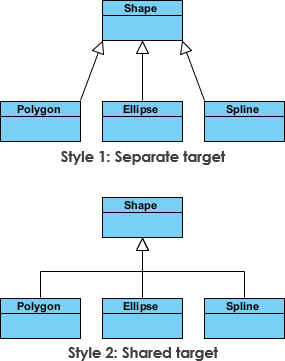
Visual Paradigm offers flexibility in how these relationships are displayed. The two styles shown in the reference image are semantically identical; they both mean “Circle is-a Shape.” However, they differ in how they group the connections visually.
By default, Visual Paradigm often displays each inheritance relationship as a separate line radiating from the subclasses to the superclass. This is the Individual Style. However, for cleaner diagrams, especially with deep hierarchies, you may prefer the Grouped Style.
In the Grouped Style, the separate lines from the subclasses merge into a single trunk before connecting to the superclass. This reduces visual clutter and clearly groups the children under a single parent.
Step 4: Toggling Between Styles
To switch between these two visual representations without breaking your model, follow these steps:
- Right-click on the Shape class in your diagram.
- Select Properties from the context menu.
- Navigate to the Style tab within the class properties dialog.
- Look for the setting labeled Inheritance style or Generalization style.
- You will see options such as Individual and Grouped.
- Select Grouped to merge the lines, or Individual to separate them.
- Click OK to apply the changes.
Pro Tip: You can also right-click specifically on the inheritance connector lines themselves to access the “Style” menu, which allows you to toggle the display for just those specific relationships.
Step 5: Verifying Semantic Equivalence
Once you have toggled the style, observe your diagram. You will notice that while the lines look different, the meaning has not changed.
The Individual Style is often preferred for simple diagrams where clarity of individual connections is paramount. It makes it immediately obvious which specific child inherits from which parent without visual ambiguity.
The Grouped Style is ideal for complex hierarchies. If you were to add a Square class that inherits from Rectangle, the grouped style helps maintain a clean tree structure, preventing the diagram from becoming a tangled web of lines.
Conclusion
Understanding how to manipulate the visual representation of inheritance in Visual Paradigm is a key skill for any system architect or developer. By mastering the Individual and Grouped styles, you ensure that your UML Class Diagrams are not only technically accurate but also aesthetically pleasing and easy to read.
Remember, the goal of modeling is communication. Whether you choose to draw separate lines or a merged trunk, you are conveying the same fundamental truth: that your software components share a common ancestry.
Related posts:
 Is UML Dead? How to Modernize Your Modeling for Agile and AI Teams
 Mastering System Design: A Deep Dive into the Inspection Management System Use Case Diagram
 Mastering UML Design: A Deep Dive into Visual Paradigm Community Edition
 From Chaos to Clarity: Mastering Complex BPMN Workflows with Visual Paradigm