Mastering Inheritance in UML Class Diagrams with Visual Paradigm
In the world of object-oriented design, inheritance (also known as Generalization) is one of the most powerful concepts for creating maintainable and scalable software architectures. It allows developers to define a common structure for a group of related items, reducing code duplication and enhancing clarity.
In this step-by-step tutorial, we will explore how to model inheritance hierarchies using Visual Paradigm. We will focus on the “is-a” relationship, how to represent abstract classes, and how to handle different visual styles for the same semantic meaning.
Understanding the Core Concept: Generalization
Before we open the software, it is crucial to understand the theory behind the diagram. A generalization is a taxonomic relationship between a more general classifier (the parent) and a more specific classifier (the child).
Key Insight: Each instance of the specific classifier is also an indirect instance of the general classifier. This means the specific classifier inherits all the features (attributes and operations) of the more general classifier.
This relationship is strictly an “is-a” relationship. For example, a Car “is a” Vehicle. A Car inherits the properties of a Vehicle, such as having an engine or wheels, but also possesses its own unique properties.
Step 1: Setting Up the Base Class (SuperClass)
To begin our tutorial, we will create a parent class that represents a general concept. In our example, we will use a Shape class.
- Open Visual Paradigm and create a new UML Class Diagram.
- From the Toolbox on the left, drag and drop a Class element onto the canvas.
- Double-click the class to rename it to SuperClass (or Shape in our context).
- Define the attributes and operations that are common to all shapes, such as color or draw().
Step 2: Creating Specialized Subclasses
Now that we have our general classifier, we need to create the specific classifiers that will inherit from it. In our diagram, these are SubClass1 and SubClass2 (e.g., Circle and Square).
- Drag two more Class elements from the Toolbox onto the canvas.
- Name them SubClass1 and SubClass2.
- Define specific attributes for these classes. For instance, SubClass1 might have a radius, while SubClass2 might have a sideLength.
Step 3: Establishing the Inheritance Relationship
This is the most critical step in modeling inheritance. We must visually represent the “is-a” relationship using the correct UML syntax.
- Select the Generalization tool from the Toolbox. In the standard UML palette, this is often represented by a line with a hollow triangle arrowhead.
- Click on SubClass1 first (the child).
- Drag the line to SuperClass (the parent) and release the mouse button.
- Repeat this process to connect SubClass2 to SuperClass.
Visual Check: You should now see a solid line with a hollow arrowhead pointing from the child element to the parent element. The arrowhead always points to the more general classifier.
Step 4: Handling Abstract Classes
Not all classes in a hierarchy are meant to be instantiated. An abstract class serves as a blueprint and cannot have instances created directly from it.
To indicate that SuperClass is abstract:
- Double-click the SuperClass element to open its editor.
- Locate the class name setting.
- Check the box labeled Is Abstract.
- Observe the class name on the diagram; it will now appear in italics.
Why this matters: In our Shape example, you might not be able to create a generic “Shape” object. You can only create specific shapes like Circles or Squares. The italics notation immediately tells developers that this class is abstract.
Step 5: Exploring Alternative Visual Styles
One of the strengths of Visual Paradigm is its flexibility. While the standard UML notation uses a solid line with a hollow triangle, some teams prefer different styles for better readability or specific diagramming conventions. The following image demonstrates two different styles for the same inheritance hierarchy.
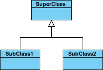
As you can see in the image above:
- Style 1 (Standard): Uses a solid line with a hollow arrowhead pointing from SubClass1 and SubClass2 to SuperClass.
- Style 2 (Alternative): Uses a different connector style (often a simple line or a specific archetype connector) but maintains the semantic meaning.
Important Note: Although the connectors are drawn differently, they are semantically equivalent. The software treats them as the same inheritance relationship. You can change the appearance of the connector without altering the underlying model logic.
Best Practices for Inheritance Diagrams
To ensure your UML diagrams remain clear and professional, keep the following tips in mind:
- Depth Matters: Avoid creating inheritance hierarchies that are too deep (more than 3-4 levels). Deep hierarchies can become hard to understand and maintain.
- Single Responsibility: Ensure that a parent class only contains attributes and behaviors that are truly common to all its children.
- Use Abstract Classes Wisely: Mark a class as abstract only if it makes no sense to instantiate it on its own.
- Consistency: Stick to one visual style for generalization across your entire project to avoid confusion.
Conclusion
By following these steps, you have successfully modeled an inheritance hierarchy in Visual Paradigm. You now understand how to connect subclasses to a super class, how to denote abstract classes with italics, and how to utilize different visual styles while maintaining semantic integrity.
Inheritance is the backbone of polymorphism and code reuse. Mastering its representation in UML class diagrams is a fundamental skill for any system architect or software engineer using Visual Paradigm.