In the modern landscape of business process management, clarity is king. Whether you are mapping a simple workflow or orchestrating complex enterprise systems, the Business Process Model and Notation (BPMN) standard provides the universal language required to communicate process logic. Visual Paradigm (VP) stands as a premier tool in this ecosystem, offering a robust environment to visualize, model, and simulate these flows. This tutorial explores the fundamental architecture of BPMN as depicted in standard diagrams and demonstrates how Visual Paradigm leverages AI assistance to streamline the creation of these models.
The Core Architecture of BPMN
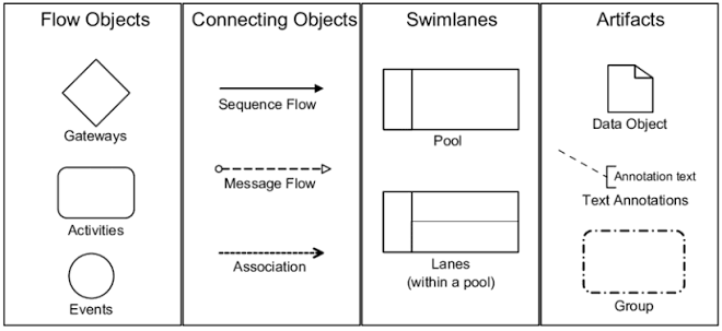
At the heart of BPMN lies a structured set of graphical symbols designed to represent the dynamic flow of a process. As shown in the reference architecture, these symbols are categorized into four primary domains: Flow Objects, Connecting Objects, Swimlanes, and Artifacts. Understanding the distinct role of each category is essential for constructing a valid and readable model.
1. Flow Objects: The Heart of the Process
Flow objects are the elements that define the actual behavior of the process. They are the most critical components for describing “what happens” and “when it happens.”
- Events: Represented by circles, events signify the start, interruption, or conclusion of a process. They are passive, meaning they do not perform work themselves but rather trigger or record an occurrence.
- Start Events: These trigger the process. They can be initiated by a message, a timer, or a signal.
- Intermediate Events: Occurring during the process, these might represent a delay, a message being received, or an error being thrown.
- End Events: These conclude the process, indicating that the work is complete, a message is sent, or the process is terminated.
- Activities: Represented by rounded rectangles, activities denote work performed within the process.
- Tasks: These are atomic units of work, such as a “User Task” (manual work) or a “Service Task” (automated work).
- Sub-processes: These are compound activities that can be expanded to reveal further detail, allowing for hierarchical modeling.
- Call Activities: These reference reusable global processes, promoting modularity and efficiency.
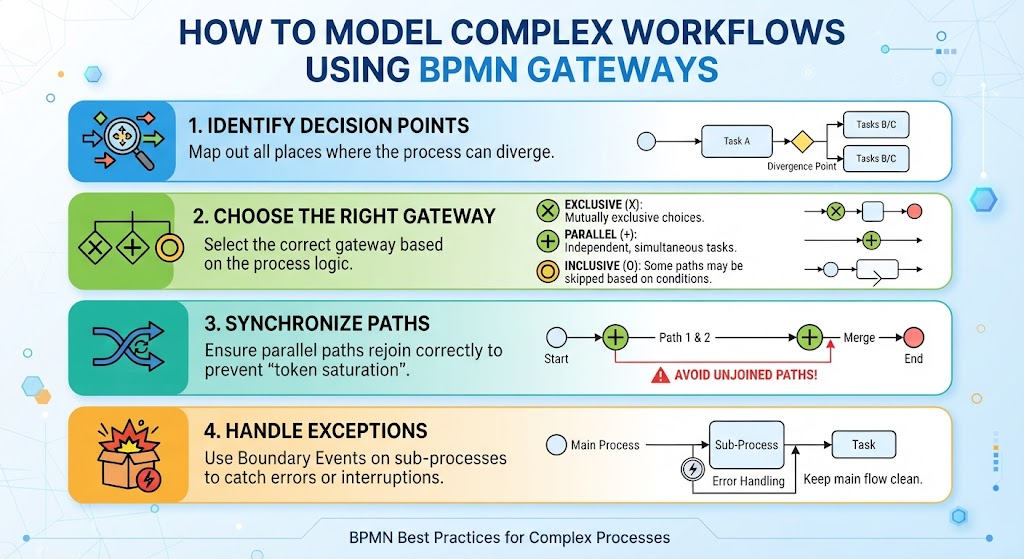
- Gateways: Represented by diamonds, gateways control the branching and merging of the process flow.
- Exclusive Gateway (XOR): Allows for only one path to be chosen based on a specific condition.
- Parallel Gateway (AND): Splits the flow into multiple paths that execute simultaneously.
- Inclusive Gateway (OR): Allows for one or more paths to execute based on conditions.
- Event-based Gateway: The path is chosen dynamically based on which event occurs first.
2. Connecting Objects: Defining the Flow
Connecting objects provide the necessary links between flow objects to define the order and communication of the process.
- Sequence Flow: A solid line with an arrowhead showing the order of activities within a single process. It dictates the sequential execution path.
- Message Flow: A dashed line with an open circle at the start and an open arrow at the end. This illustrates communication between different participants (pools), representing messages sent from one entity to another.
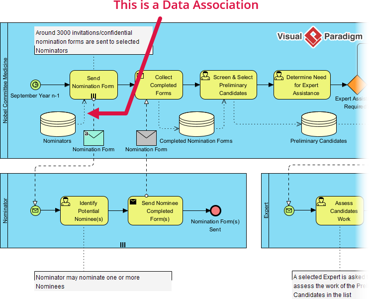
- Association: A dashed line that links artifacts (like data or text) to flow objects, providing context without affecting the process flow.
3. Swimlanes: Organizing Responsibility
Swimlanes are structural containers used to organize the diagram and assign responsibility. They answer the question: “Who is doing this?”
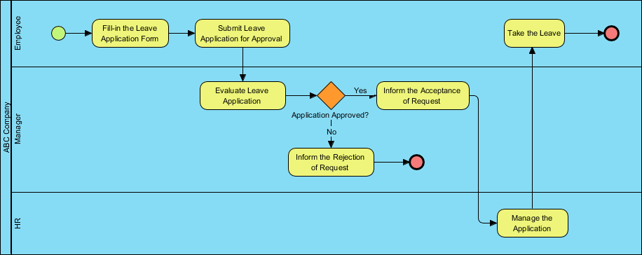
- Pools: Represent distinct participants, such as an organization, a department, or a system. They act as the boundary for a process.
- Lanes: These are sub-divisions within a pool, used to further categorize roles, teams, or individuals. Lanes allow for a clear vertical segregation of tasks within a single participant.
4. Artifacts: Adding Context
Artifacts provide additional information to the model without altering its logic.
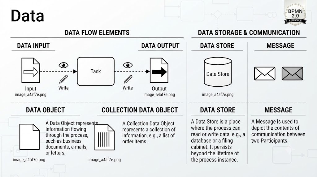
- Data Objects: Represent the data consumed or produced by an activity.
- Text Annotations: Used to add explanatory notes or comments to the diagram.
- Groups: Visual containers that group a set of elements together for better organization.
Tooling of the Visual Paradigm BPMN + AI Assisted
While manual modeling provides a deep understanding of process logic, modern tools like Visual Paradigm have integrated Artificial Intelligence to accelerate the design phase. This integration transforms the modeling experience from a purely manual drafting task into a collaborative, intelligent engineering process.
The AI-Assisted Modeling Workflow
Visual Paradigm’s AI capabilities allow users to move beyond drawing boxes and connecting lines. The workflow typically involves the following steps:
- Natural Language to Diagram: Users can input a description of their business process in plain English. The AI engine parses this text to identify potential events, activities, and gateways, automatically generating a preliminary BPMN diagram.
- Semantic Analysis: The AI analyzes the context of the text to suggest the correct types of gateways and connecting objects. For instance, if the text describes a decision point, the AI might suggest an Exclusive Gateway (XOR).
- Validation and Refinement: The AI assists in checking the model for logical errors, such as dead ends (flows that stop without an end event) or unconnected nodes, offering suggestions for correction.
Benefits of AI in BPMN Modeling
- Speed: Reduces the time required to create initial drafts from hours to minutes.
- Standardization: Ensures that the generated diagrams adhere strictly to BPMN 2.0 syntax rules, reducing the likelihood of modeling errors.
- Accessibility: Lowers the barrier to entry for non-experts, allowing stakeholders to visualize processes without needing deep knowledge of the notation’s syntax.
Conclusion
By mastering the core concepts of Flow Objects, Connecting Objects, Swimlanes, and Artifacts, you build a solid foundation for business process modeling. When combined with the power of Visual Paradigm’s AI-assisted tooling, these concepts become the building blocks for efficient, accurate, and scalable enterprise architecture.