


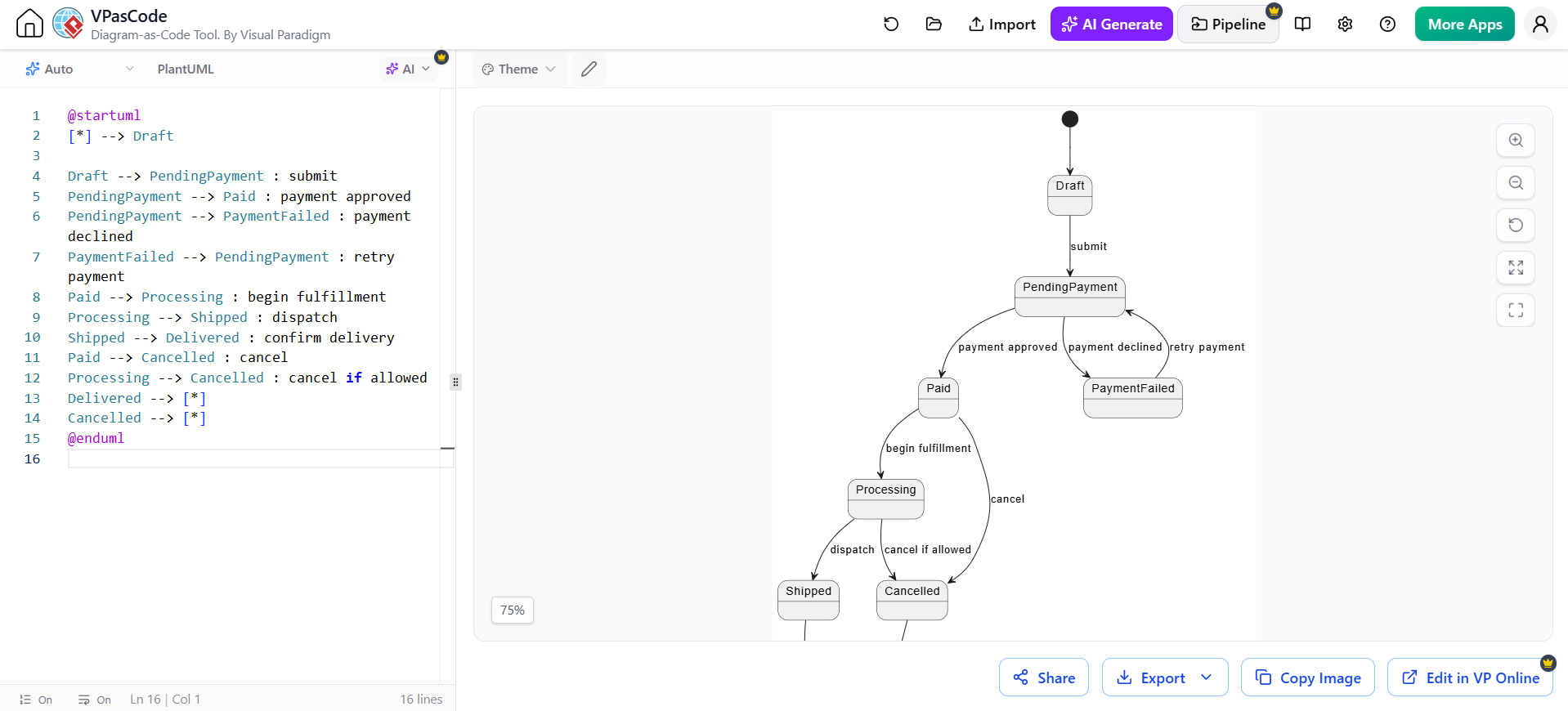
In the complex world of system architecture, few things are as critical as understanding how an object behaves under different conditions. Whether you are designing a payment gateway, a subscription service, or a workflow engine, the state of an entity often dictates its future possibilities. This tutorial explores State-Machine Diagrams, a powerful UML modeling technique, and demonstrates how to implement them efficiently using VPasCode within Visual Paradigm.
Understanding State-Machine Diagrams
A State-Machine Diagram (or Statechart Diagram) is a behavioral diagram that describes how an entity responds to events by moving between states. Unlike a simple flowchart, a state machine captures the fact that the same event (e.g., “cancel”) might have different consequences depending on the current state of the object.
These diagrams are invaluable when an object’s behavior depends strongly on its current state. Common examples include:
- Order Lifecycle: Draft → Pending Payment → Shipped → Delivered.
- User Accounts: Registered → Verified → Suspended.
- Support Tickets: Open → In Progress → Resolved.
- Job Execution: Queued → Running → Failed.
The Power of Code-First Modeling
Traditionally, drawing state machines involves dragging and dropping boxes and drawing arrows, which can be time-consuming and prone to layout errors. VPasCode (Visual Paradigm as Code) changes this paradigm. It allows developers and architects to define their system’s lifecycle logic using a concise text-based syntax, which is then rendered automatically into a visual diagram.
This approach offers several advantages:
- Version Control: Diagrams become text files that can be diffed, merged, and tracked in Git.
- Speed: Typing logic is often faster than manual drawing.
- Consistency: The layout engine ensures a professional look without manual tweaking.
Step-by-Step: Modeling an Order Lifecycle
Let’s walk through a real-world example: an Online Order. We will model the journey from a “Draft” order to being “Shipped” or “Cancelled”.
1. Defining the States
First, we need to identify the distinct phases an order goes through. In our example, we have:
- Draft: The initial state when the order is created.
- PendingPayment: The order is submitted, waiting for payment.
- PaymentFailed: The payment attempt was unsuccessful.
- Paid: The payment was successful.
- Processing: The order is being fulfilled.
- Shipped: The item has been dispatched.
- Delivered: The customer received the item.
- Cancelled: The order was terminated.
2. Defining Transitions and Events
Next, we define how the object moves between these states. A transition is triggered by an Event. The syntax generally follows the format: SourceState --> TargetState : EventTrigger.
Consider the PendingPayment state. From here, the system can go in two directions:
- If payment is approved, move to Paid.
- If payment is declined, move to PaymentFailed.
3. The VPasCode Implementation
Here is how we translate the logic above into VPasCode syntax. Notice how we use the
@startuml</code> and <code>@endumlmarkers to encapsulate the diagram definition.
@startuml
[*] --> Draft

Draft --> PendingPayment : submit
PendingPayment --> Paid : payment approved
PendingPayment --> PaymentFailed : payment declined
PaymentFailed --> PendingPayment : retry payment

Paid --> Processing : begin fulfillment
Processing --> Shipped : dispatch
Shipped --> Delivered : confirm delivery
Paid --> Cancelled : cancel
Processing --> Cancelled : cancel if allowed
Delivered --> [*]
Cancelled --> [*]
@enduml
When you input this code into the VPasCode editor, Visual Paradigm instantly renders the state machine on the right-hand side, handling all the positioning and connection logic for you.
Analyzing the Diagram Logic
Let’s break down the specific logic shown in the generated diagram to understand the architectural decisions made:
Handling Payment Failures (Self-Looping Logic)
Notice the transition from PaymentFailed back to PendingPayment. This represents a “retry” mechanism. In a robust system, a payment failure shouldn’t immediately kill the order; it should allow the user to correct their information and try again. The code PaymentFailed --> PendingPayment : retry payment captures this resilience.
Conditional Transitions
Look at the transition to the Cancelled state. It can be triggered from multiple states:
Paid --> Cancelled : cancelProcessing --> Cancelled : cancel if allowed
The second transition includes a guard condition or specific context (“if allowed”). This implies that once an order is in the “Processing” phase, cancellation might be restricted by business rules (e.g., the item has already been packed). The text-based syntax allows you to annotate these nuances clearly.
Termination Points
The diagram uses the [] symbol to represent the final state. In the code, Delivered --> [] and Cancelled --> [*] indicate that once the order is delivered or cancelled, the lifecycle for that specific order instance ends.
Conclusion
State-Machine Diagrams are essential for modeling the lifecycle of any object with a distinct workflow. By leveraging VPasCode, architects can write these diagrams as code, ensuring they remain maintainable, version-controlled, and easy to read. Whether you are mapping out a simple subscription flow or a complex device lifecycle, the “code-first” approach streamlines the documentation process.
Start experimenting with VPasCode today to visualize your system’s behavior with clarity and precision.
Related posts:
 Bridging the Gap: From Static Artifacts to Living Systems
 UML & AI: Supercharging Agile Modeling for Modern Software Architecture
 The Evolution of UML: Mastering the Modern Architecture Stack from Drag-and-Drop to Diagrams as Code
 Mastering the Modern Modeling Workflow: AI Chatbot vs. VPasCode in Visual Paradigm