Designing the architecture for a complex system like a Library Management System requires a clear blueprint of how users interact with the software. In the world of software engineering, Use Case Diagrams are the gold standard for visualizing these interactions. They bridge the gap between technical requirements and user needs.
This tutorial explores how to model a comprehensive library system using PlantUML within the VPasCode environment. We will break down the system into actors, use cases, and the critical relationships that bind them together, ensuring your system logic is sound before a single line of code is written.
1. Identifying the Actors and System Scope
Before drawing lines and ovals, we must define the boundaries of our system and the entities that interact with it. In our example, the system boundary is the Library Management System.
The Actors
Actors represent the roles of users or external systems that initiate actions. In a robust library system, we distinguish between human actors and external services:
- Member: The primary user who wants to find, borrow, and return books.
- Librarian: The administrator responsible for managing the catalog and handling specific member issues.
- Payment Service: An external system dependency required to process fines or payments securely.
- Notification Service: An external system dependency used to send alerts about overdue books.
2. Defining Use Cases and Functional Requirements
Use cases describe specific functionalities the system must provide. Based on the system requirements, we identify the following core functions:
- Search Catalog: Allows members to find books by title, author, or ISBN.
- Borrow Book: The process of checking out a book for a specific period.
- Return Book: The process of bringing a book back to the library.
- Manage Catalog: Allows librarians to add, remove, or update book records.
- Pay Fine: Handles the transaction for overdue penalties.
- Send Overdue Notification: The automated alert system for late returns.
3. Modeling Relationships: Include vs. Extend
The most critical part of a Use Case Diagram is defining the logic flow. We use two primary relationships: <<include>> and <<extend>>.
The <<include>> Relationship
An include relationship signifies that a base use case must perform the included behavior to be completed. It is a mandatory step.
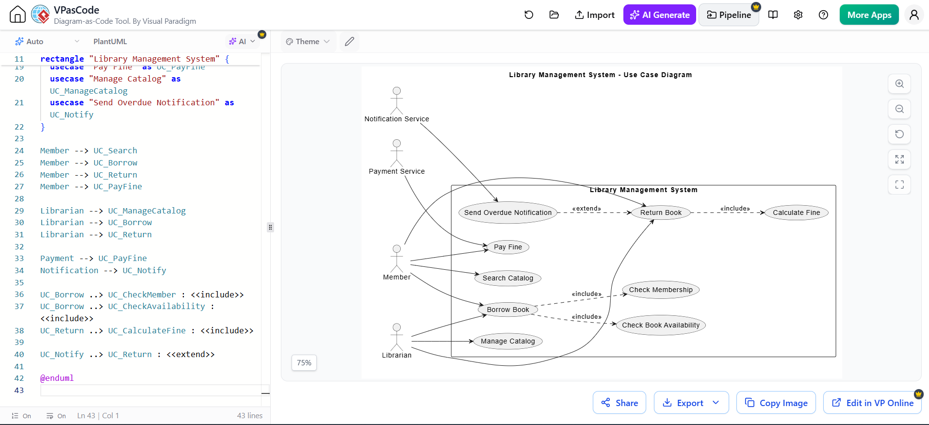
- Borrow Book <<include>> Check Membership: You cannot borrow a book without verifying the member’s status first.
- Borrow Book <<include>> Check Book Availability: The system must verify the book is not already checked out.
- Return Book <<include>> Calculate Fine: Every return triggers a calculation to see if the book is late (even if the fine is zero).
The <<extend>> Relationship
An extend relationship indicates that a base use case may perform the extending behavior under specific conditions. It is optional or conditional logic.
- Return Book <<extend>> Send Overdue Notification: This only happens if the Calculate Fine step determines the book is actually overdue. If the book is returned on time, no notification is sent.
4. Implementation: Writing the PlantUML Code
In VPasCode, you can define your entire system architecture using a simple text-based language. This approach allows for version control and rapid prototyping. The code below demonstrates how to define the system rectangle, the actors, and the complex relationships including the external service interactions.
@startuml
rectangle "Library Management System" {
  usecase "Pay Fine" as UC_PayFine
  usecase "Manage Catalog" as UC_ManageCatalog
  usecase "Send Overdue Notification" as UC_Notify
}

' Member Interactions
Member --> UC_Search
Member --> UC_Borrow
Member --> UC_Return
Member --> UC_PayFine

' Librarian Interactions
Librarian --> UC_ManageCatalog
Librarian --> UC_Borrow
Librarian --> UC_Return

' External Service Interactions
Payment --> UC_PayFine
Notification --> UC_Notify

' Include Relationships (Mandatory Steps)
UC_Borrow ..> UC_CheckMember : <>
UC_Borrow ..> UC_CheckAvailability : <>
UC_Return ..> UC_CalculateFine : <>

' Extend Relationships (Conditional Logic)
UC_Notify ..> UC_Return : <>

' Note: The diagram logic implies that "Send Overdue Notification" extends "Return Book"
' specifically when the "Calculate Fine" condition is met.

@enduml 5. Leveraging VPasCode for Diagram Management
The screenshot of the VPasCode interface reveals a powerful workflow: Code-to-Diagram. On the left side, the editor displays the raw PlantUML syntax. On the right, the rendered diagram updates in real-time. This separation of concerns allows developers to:
- Refactor Logic Easily: Changing a relationship from include to extend is as simple as editing one line of text.
- Maintain Documentation: The code itself serves as up-to-date documentation, ensuring the visual diagram never drifts from the actual system requirements.
- Collaborate: Teams can review system architecture using standard code review tools before the visual diagram is even generated.
By mastering these modeling concepts and tools, you ensure that your Library Management System is built on a foundation of clear, logical, and well-communicated requirements.