In the modern landscape of software engineering, the bridge between abstract requirements and concrete system architecture is often the most challenging gap to bridge. Traditionally, this required manual drafting of complex UML diagrams, a process prone to syntax errors and human inconsistency. However, a new paradigm is emerging where AI acts as a collaborative architect, translating natural language directly into rigorous system models.
This tutorial explores the architecture behind AI-driven diagramming, specifically focusing on how tools like Visual Paradigm utilize Conversational Generation to transform a simple text description into a professional Activity Diagram. We will analyze the workflow shown in the system interface, deconstruct the modeling logic, and demonstrate how to leverage this technology for rapid prototyping.
The Architecture of Conversational Modeling
The system depicted in the interface operates on a sophisticated pipeline that blends Natural Language Processing (NLP) with formal modeling syntax. Instead of the user manually placing nodes and connecting lines, the AI interprets the semantic intent of the user’s prompt.
The process follows three core architectural principles:
- Intent Recognition: The AI parses the input text to identify the domain (e.g., Order Processing), the actors (e.g., Customer, System), and the primary actions.
- Structural Mapping: Based on the intent, the system selects the appropriate diagram type. In this case, a linear flow with decision points requires an Activity Diagram.
- Graph Generation: The AI instantiates the visual nodes (Start, Action, Decision, End) and draws the control flow edges, including conditional logic (Yes/No branches).
Deconstructing the Workflow: The Order Processing System
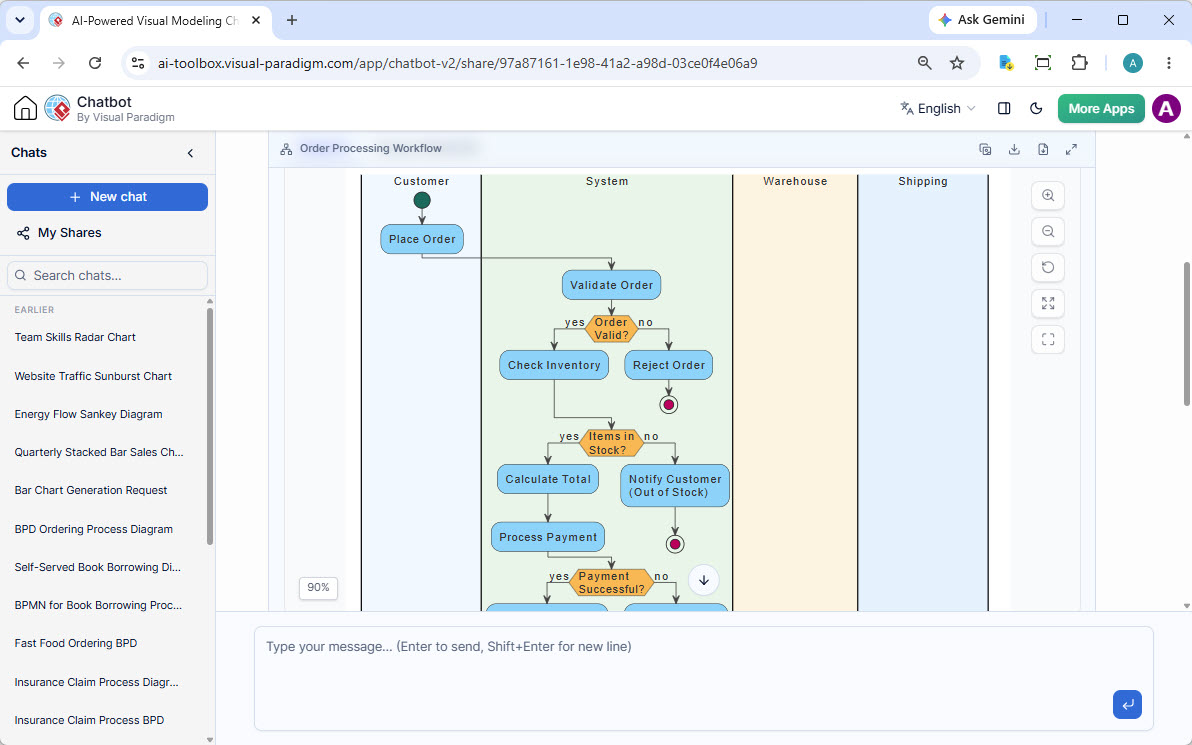
Let’s analyze the diagram generated in the screenshot. This represents a classic Order Processing Workflow. The diagram is organized into Swimlanes, a modeling technique used to show which actor is responsible for which step.
1. Swimlane Analysis
The diagram is vertically partitioned to clearly delineate responsibilities:
- Customer: The external trigger. This lane contains the initial action “Place Order.”
- System: The core logic processor. This is the most active lane, containing validation, inventory checks, and payment processing.
- Warehouse & Shipping: These lanes represent backend dependencies. While the “System” lane drives the logic, these lanes represent the physical execution environment.
2. Logic Flow and Decision Nodes
The diagram utilizes standard UML Decision Nodes (represented by orange diamonds) to handle conditional logic. This is critical for system resilience. The flow moves as follows:
- Validation: The system first checks if the Order Valid?. If no, it immediately terminates the process via the Reject Order path.
- Inventory Check: If valid, the system proceeds to Check Inventory. This leads to a second decision: Items in Stock?
- Branching Logic:
- Yes: The system calculates the total and processes payment.
- No: The system executes a fallback action, Notify Customer, and terminates.
- Payment Verification: The final decision node checks Payment Successful?. This ensures financial integrity before the order is committed.
Technical Implementation: VPasCode
One of the most powerful features of this AI modeling environment is VPasCode (Visual Paradigm as Code). This allows developers to view the underlying syntax of the diagram. Understanding this code is essential for “Iterative Model Derivation,” where you might want to modify the logic manually after the AI generates the initial draft.
Here is the structural representation of the logic flow seen in the diagram, translated into a pseudocode representation of the VPasCode syntax:
@startuml
title Order Processing Workflow

rectangle "Customer" {
    start
    :Place Order;
}

rectangle "System" {
    :Validate Order;
    if (Order Valid?) then (yes)
      :Check Inventory;
      if (Items in Stock?) then (yes)
        :Calculate Total;
        :Process Payment;
        if (Payment Successful?) then (yes)
          ' (End of process logic)
        else (no)
          ' (Handle payment failure)
        endif
      else (no)
        :Notify Customer (Out of Stock);
      endif
    else (no)
      :Reject Order;
    endif
}
@enduml
Key Modeling Concepts
- Control Flow: The arrows represent the sequence of operations. The diagram clearly shows that “Reject Order” is a terminal state, while “Place Order” is the trigger.
- State Transition: The red circles indicate the End State. The diagram correctly handles multiple exit points (e.g., if the order is rejected, or if stock is missing).
- Modularity: By separating “Warehouse” and “Shipping” into their own swimlanes, the model remains clean even though the “System” lane drives the logic. This separation is vital for microservices architecture where these might be different API endpoints.
Conclusion
The transition from manual drawing to AI-assisted generation is not just about speed; it is about consistency and accuracy. By offloading the syntax and layout to the AI, the system architect can focus on the logic flow and business rules. As demonstrated by the Order Processing Workflow, the AI successfully captured complex branching logic and swimlane responsibilities, providing a robust foundation for further development.
Whether you are building a simple workflow or a complex distributed system, tools that combine conversational interfaces with rigorous UML standards are redefining how we design software.