


In modern software engineering, maintaining code that is scalable, testable, and decoupled is a paramount goal. One of the most enduring architectural patterns designed to achieve this is the Model-View-Controller (MVC) pattern. By separating an application into three interconnected components—Model, View, and Controller—developers can manage complexity and allow for independent changes to the user interface without disrupting the underlying business logic.
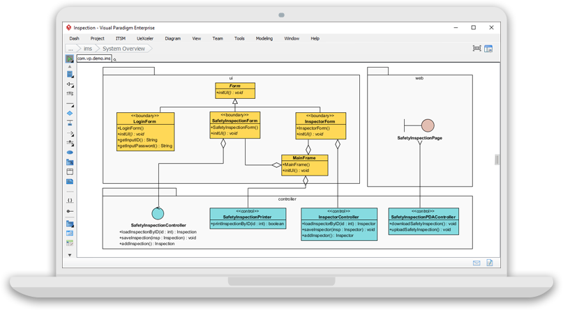
In this tutorial, we will deconstruct the architecture displayed in the provided Visual Paradigm screenshot. We will explore how a “Safety Inspection” application is structured using this pattern, analyzing the specific roles of the Form (View), SafetyInspectionController (Controller), and the data models.
1. Deconstructing the Architecture
The diagram illustrates a classic Object-Oriented design where responsibilities are strictly partitioned. Let’s break down the three distinct layers visible in the system overview.
The View Layer: <> Form
The View is the visual representation of the data to the user. In the provided diagram, this is encapsulated within the Form component. Notice that this component is stereotyped as «boundary», indicating it handles the interaction between the system and the external user.
- Sub-classes: The diagram shows specialized forms like
LogInFormandSafetyInspectionForm. - Responsibilities: These classes manage UI events. For instance, the
LogInFormcontains methods likelogin()andgetInputID(). Crucially, they do not perform business logic; they simply gather input and display results.
The Controller Layer: <> Controller
The Controller acts as the intermediary between the View and the Model. It receives input from the user (via the View), processes it, and coordinates the response. In the diagram, this role is filled by the controller package, which contains three specific controllers:
- SafetyInspectionController: The main orchestrator. It handles the primary logic for loading and saving inspection data.
- SafetyInspectionPrinter: A specific controller dedicated to the side effect of generating reports or printouts.
- InspectorController & SafetyInspectionPDACcontroller: Specialized controllers likely handling data persistence or specific inspector workflows.
The Model Layer: <> MainForm & Data
While less explicitly labeled as “Model” in the bottom section compared to the View and Controller, the MainForm (stereotyped as «entity») represents the core data structure or business entity. It holds the state of the safety inspection (e.g., the list of inspectors or the inspection status) and is agnostic of how the data is presented on the screen.
2. Understanding the Relationships
The true power of the MVC pattern lies in how these components interact. The diagram uses standard UML dependency and association lines to define these relationships.
View to Controller Dependency
Observe the connection between the SafetyInspectionForm and the SafetyInspectionController. The View holds a reference to the Controller. When a user clicks a button in the SafetyInspectionForm, it triggers a method call on the Controller. This ensures the View remains “dumb”—it doesn’t know how to save the data, only that it needs to ask the Controller to do it.
Controller to Entity Association
The Controller is connected to the MainForm (Entity). This is where the business logic lives. The Controller retrieves data from the Entity, processes it (perhaps validating the input), and may modify the Entity’s state.
3. Implementation Best Practices in Visual Paradigm
When designing such a system in Visual Paradigm, it is critical to maintain the “One Responsibility” principle. If you find a method inside SafetyInspectionController that is directly manipulating the visual properties of the SafetyInspectionForm (like changing the font size or hiding a button), you have violated the MVC separation of concerns.
4. Conclusion
The architecture shown in the screenshot demonstrates a clean separation of concerns. By isolating the UI logic (Form), the workflow logic (Controller), and the data structure (MainForm), the system becomes significantly easier to test and maintain. If the user interface needs to change from a desktop window to a web view, the Controller and Model can remain largely untouched, requiring only a new View implementation.
Related posts:
 Bridging the Gap: From Static Artifacts to Living Systems
 Mastering PlantUML: A Deep Dive into Composition and Aggregation Relationships
 Mastering UML Modeling: A Step-by-Step Guide to Class vs. Object Diagrams
 Mastering UML Class Diagrams: A Step-by-Step Guide to University Information System Modeling