In the world of Business Process Management (BPM), moving from a high-level overview to an actionable process model is a critical transition. This tutorial explores the architecture of a Level 2 Process Description, specifically focusing on the Cross-functional Customer Service Flow. We will dissect how to add necessary context—such as roles, systems, and rules—without getting bogged down in the operational minutiae required for automation.
1. The Architecture of a Level 2 Diagram
A Level 1 diagram is often a “black box” view, showing only the start and end of a journey. A Level 2 diagram, however, opens that box. Its primary purpose is to bridge the communication gap between business stakeholders (who care about the work) and IT professionals (who care about the systems and logic).
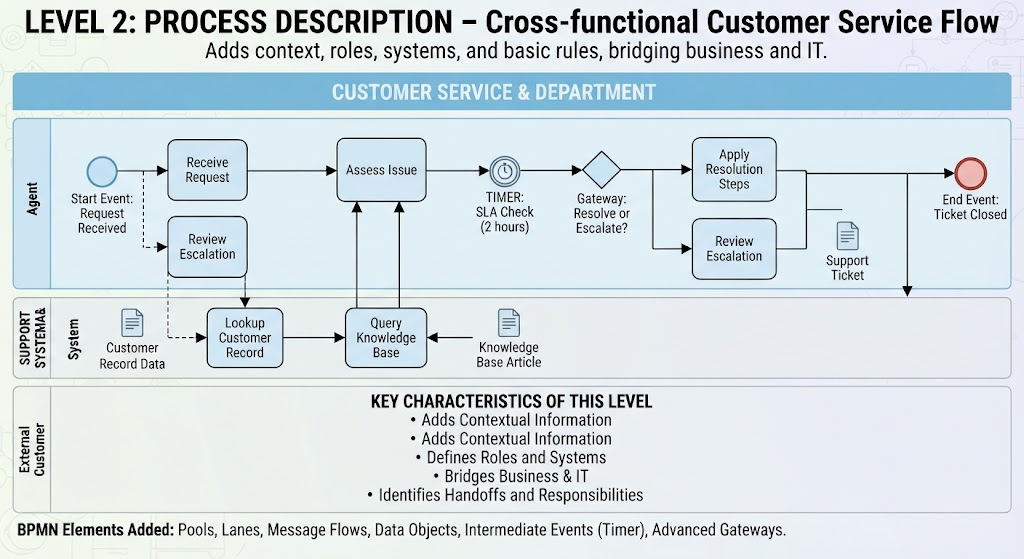
The diagram you are analyzing represents the Cross-functional Customer Service Flow. Unlike a standard swimlane diagram, this uses specific BPMN 2.0 extensions to create a rich, context-aware map. It is designed to be comprehensive enough for compliance and audit documentation, yet abstract enough to remain readable.
2. Structuring the Canvas: Pools and Lanes
The visual foundation of this model is the Pool (labeled “Customer Service & Department”), which contains the entire process scope. Within this pool, we utilize Lanes to assign responsibility. This is crucial for identifying handoffs.
- Agent Lane: This represents the human actor. It contains the decision-making activities like Assess Issue and Apply Resolution Steps.
- System Lane (Support System A & System): This lane represents the IT infrastructure. Activities here, such as Lookup Customer Record and Query Knowledge Base, are typically automated or triggered by the agent.
- External Customer Lane: This represents the entity initiating the process, often the trigger for the “Start Event.”
Key Concept: Handoffs
Notice the vertical lines connecting the Agent and System lanes. These are not just connectors; they are handoffs. They indicate that a human has initiated a request for data, and the system must respond before the human can proceed to the next step.
3. Decoding the BPMN Elements
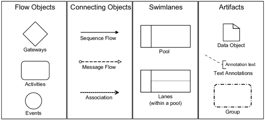
To achieve the “Extended Flow Chart” status, we utilize specific BPMN 2.0 elements that go beyond basic flow control.
A. Events: The Pulse of the Process
- Start Event (Circle): Represents the “Request Received.” This is the entry point into the system.
- Intermediate Event (Timer): The Timer: SLA Check is a vital addition. It indicates a time-based monitoring mechanism. The process waits for 2 hours; if the issue isn’t resolved by then, the flow changes. This adds the “rule” component to the model.
- End Event (Red Circle): Marks the successful closure of the “Ticket Closed.”
B. Gateways: Logic and Decision Making
The diagram introduces a Gateway (Diamond) labeled “Resolve or Escalate?”. This is an Exclusive Gateway (XOR). It acts as a traffic controller:
- If the agent can resolve it, the flow goes to Apply Resolution Steps.
- If the agent cannot resolve it, the flow branches to Review Escalation.
C. Data Objects: The Information Flow
One of the most distinct features of this architecture is the inclusion of Data Objects (represented by the sheet icon). These visualize the data artifacts required for the process.
- Customer Record Data: The input required to start the lookup.
- Knowledge Base Article: The output of the system query, used to inform the agent.
- Support Ticket: The document generated if an escalation is required.
4. The Role of Message Flows
While standard sequence flows (solid lines) show the order of execution within a single participant, Message Flows (dashed lines) represent interactions between participants. In this diagram, the dashed line from the Agent to the System indicates that the Agent is sending a request (e.g., “Look up ID”) and the System is responding (e.g., “Here is the record”).
5. Tooling: Visual Paradigm BPMN + AI Assisted
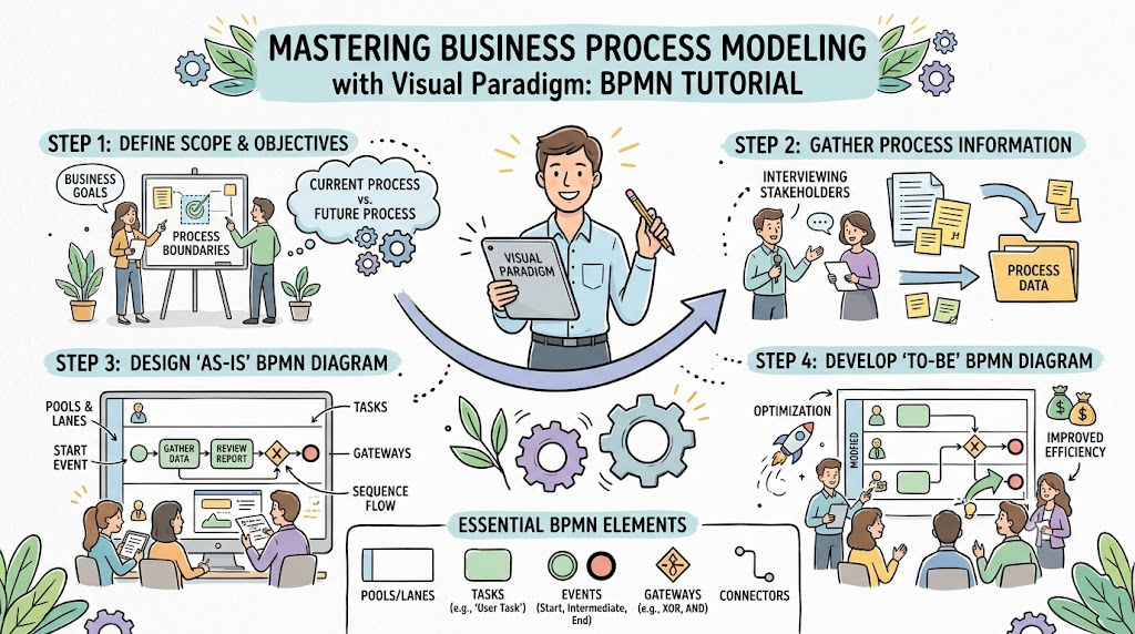
Creating a model this rich requires precision. Modern modeling tools like Visual Paradigm have evolved to support this complexity through AI-Assisted Modeling.
Why AI is Essential for Level 2 Modeling
Manual BPMN modeling is prone to errors and inconsistencies. By integrating AI into Visual Paradigm, the modeling process becomes intelligent:
- Contextual Metadata Generation: AI can analyze natural language process descriptions and automatically suggest appropriate BPMN elements (e.g., suggesting a Timer Event if the text mentions “2-hour SLA”).
- Pattern Recognition: AI algorithms can detect loops and potential dead-ends in the logic, ensuring the flow is valid before it is even published.
- Automation Readiness: While Level 2 is not for full automation, AI can tag specific activities as “Automatable” or “Manual,” preparing the model for future transformation.
Workflow with AI-Assisted Tools
- Ingest Text: Load a business requirement document describing the customer service flow.
- AI Suggestion: The tool suggests creating a Pool for “Customer Service” and a Lane for “System.”
- Auto-Modeling: The AI proposes the sequence: Start Event → Task → Gateway → End Event.
- Refinement: The modeler manually adds the specific Data Objects and Intermediate Timer Events to add the necessary context.
Conclusion
The Level 2 Process Description is the “sweet spot” for process documentation. It provides enough detail for IT to understand system integration points and for Business to verify compliance, without overwhelming the reader with low-level operational data. By leveraging tools like Visual Paradigm with AI assistance, organizations can build these robust, cross-functional models efficiently.