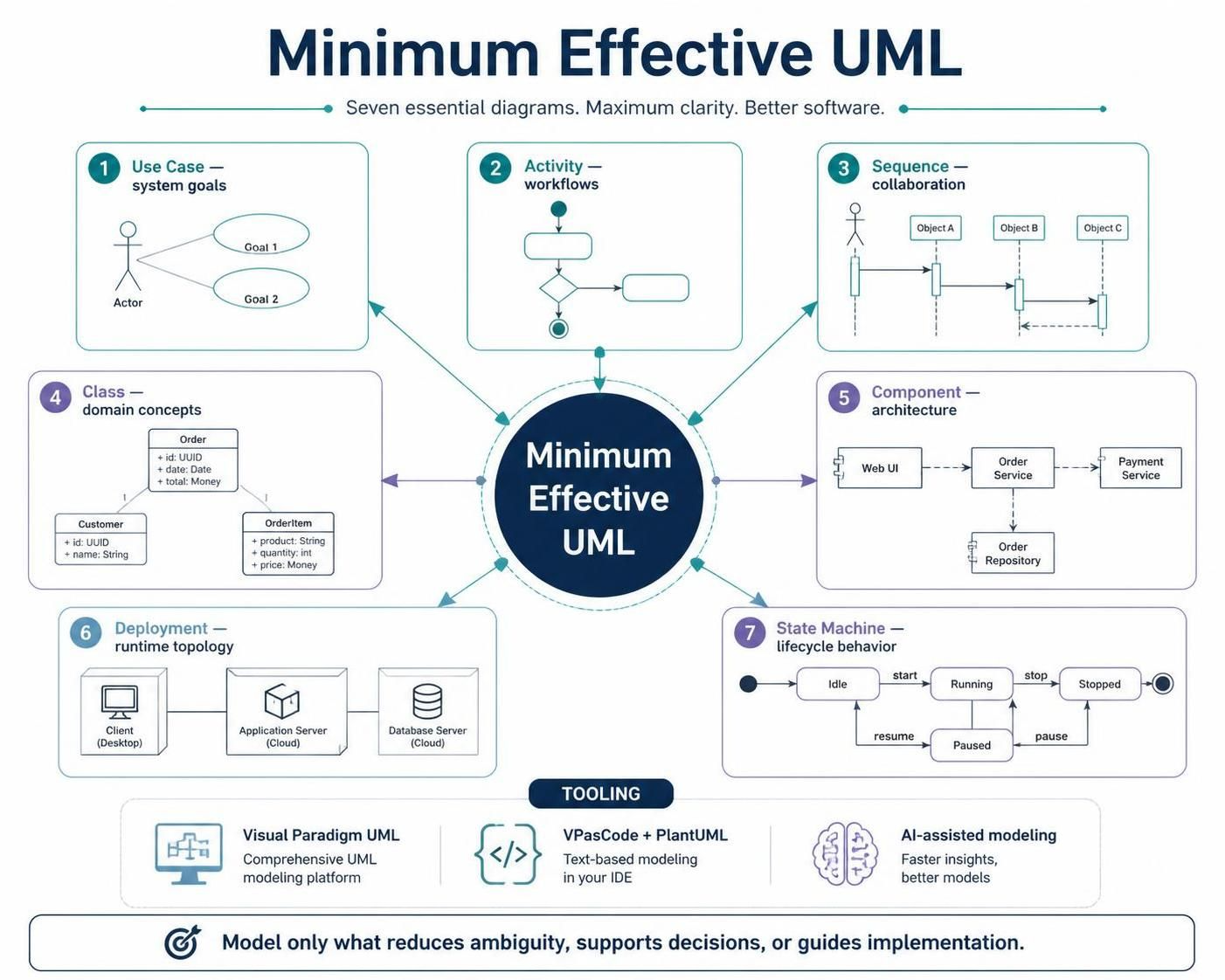
In the world of software architecture, clarity is currency. When you need to visualize the internal structure of a system and how its parts interact, the UML Component Diagram is your most powerful tool. This diagram type describes the structural organization of a system by breaking it down into manageable modules called components.
Using industry-standard tooling like Visual Paradigm, you can move from abstract concepts to a concrete blueprint. Below, we will analyze a real-world scenario involving a “Terminal” system, breaking down the specific elements shown in the diagram: Components, Ports, Provided Interfaces, and Required Interfaces.
1. The Big Picture: Understanding Components
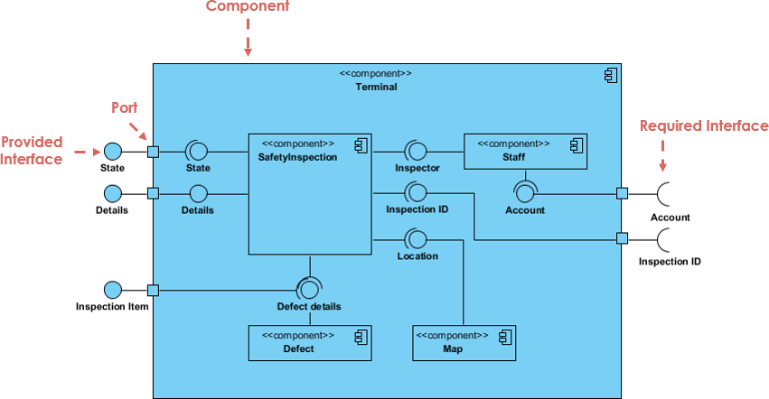
At the heart of this diagram is the blue container labeled Terminal. In UML, a component is a modular, deployable, and replaceable part of a system. It encapsulates implementation details and exposes functionality through interfaces.
- Visual Representation: In Visual Paradigm, a component is typically drawn as a rectangle with a specific icon in the top-right corner (resembling a plug or a file).
- Role: The “Terminal” component acts as the system boundary. It contains several sub-components like
SafetyInspection,Staff,Defect, andMap.
2. The Gateway: Ports and Interfaces
One of the most critical concepts in component modeling is the separation of “what” a component does from “how” it connects. This is achieved using Ports and Interfaces.
Provided Interfaces (The “Lollipop”)
Look at the left side of the SafetyInspection component. You will see small circles labeled State and Details. These are Provided Interfaces.
- The Concept: This represents a service the component offers to the outside world. It says, “If you need information about the current State or Details, connect here.”
- The Visual: In UML, this is drawn as a circle (a “lollipop”) attached to a small square box called a Port.
- Context: The
Terminalsystem exposes these ports to the outside, allowing external systems to interact with the internalSafetyInspectionlogic without needing to know how that logic is implemented.
Required Interfaces (The “Socket”)
Now, look at the right side of the diagram. You will see semi-circles labeled Account and Inspection ID. These are Required Interfaces.
- The Concept: This represents a dependency. The component needs a service to function. It says, “To work correctly, I need access to an Account and an Inspection ID.”
- The Visual: This is drawn as a half-circle (a “socket”) attached to a Port.
- Connection: The diagram shows lines connecting the “Socket” on the
Terminalto the “Lollipop” on the internalStaffcomponent. This signifies that the Terminal’s requirement for an Account is fulfilled by the Staff component’s provided service.
3. Connecting the Dots: Assembly Connectors
The lines connecting the circles and squares are called Assembly Connectors. They represent the wiring of the system.
// Conceptual Logic of the Diagram:

[External System] --(connects to)--> [Terminal Port] --(matches)--> [Staff Component's Provided Interface]
When you see a line connecting a Required Interface (socket) to a Provided Interface (lollipop), it creates a contract. The Terminal component relies on the Staff component to manage accounts. Similarly, the SafetyInspection component connects to the Defect and Map components to retrieve defect details and location data.
4. Best Practices with Visual Paradigm
When modeling in Visual Paradigm, maintaining a clean hierarchy is essential. Notice how the diagram uses nested components. The Terminal is a composite component that houses the logic for SafetyInspection, Defect, and Map. This structure helps in:
- Modularization: Isolating specific business logic (like Map handling) into its own sub-component.
- Dependency Management: Clearly defining which sub-components talk to each other versus which talk to the outside world.
Conclusion
By mastering the syntax of Ports, Provided Interfaces, and Required Interfaces, you create a diagram that is not just a drawing, but a functional specification. It tells developers exactly where to plug in their code and what external services they must consume to make the system work.