


In the realm of software engineering and system architecture, distinguishing between the abstract design and the concrete reality is crucial. This tutorial explores the concept of Object Diagrams, utilizing a practical example of a Smart Lighting system to demonstrate how specific instances operate within a defined class structure.
From Class to Instance: The Core Concept
Before diving into the visualization, we must understand the fundamental difference between a Class and an Object. Think of a Class as an architectural blueprint. It defines the rules, the structure, and the attributes (like location, brightness, color) but does not exist physically in the house. It is just the general idea.
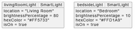
An Object, however, is the “real thing.” It is a specific instance of that class created in memory at a specific point in time. While the blueprint remains the same, the actual lights in a home can have unique, distinct states. For example, you might have a bright light in the living room and a dim, warm light by the bedside. These are two different objects created from the same SmartLight class.
Visualizing the Architecture
Visual Paradigm, a powerful modeling tool, allows us to represent these relationships visually. An Object Diagram is a snapshot of the system at a specific moment. It shows:
- The Class Name (e.g., SmartLight).
- The Instance Name (e.g., livingRoomLight).
- The Attribute Values currently held by that specific instance.
Below, we break down the specific architecture of our two smart lights, showing how they share structure but differ in state.
Instance 1: The Living Room Light
The first object, livingRoomLight, represents a device actively controlling the main area of the home. It inherits the structure of the SmartLight class but holds specific data:
- Location: “Living Room”
- Brightness: Set to
80percent, indicating high visibility. - Color: Defined by the hex code
"#FF5733", creating a vibrant red-orange hue. - Status:
isOn = true, meaning the device is currently active.
Instance 2: The Bedside Light
The second object, bedsideLight, represents a device designed for relaxation. While it is technically the same class of device, its current state is vastly different:
- Location: “Bedroom”
- Brightness: Set to a low
10percent, suitable for winding down. - Color: Defined by the hex code
"#FFD1A9", providing a soft, soothing peach tone. - Status:
isOn = true, indicating it is powered on but dimmed.
Implementing the Model with PlantUML
Modern modeling tools often use code-based syntax to generate diagrams. PlantUML is a popular language that allows developers to describe diagrams using text. The following code demonstrates how to programmatically define these two objects and render them into a visual diagram.
The syntax uses the object keyword to define an instance, followed by the class name (e.g., : SmartLight). Inside the curly braces { }, we define the specific attribute values for that instance.
Code Structure Explanation
- Declaration:
object "livingRoomLight : SmartLight"creates the object box and identifies it as an instance of the SmartLight class. - Attributes: The lines inside the block, such as
brightnessPercentage = 80, assign specific values to the attributes defined in the class. - Rendering: When processed by a tool like VPasCode or a PlantUML server, this text is converted into the graphical boxes shown in the diagram.
Conclusion
Understanding Object Diagrams is vital for system architects because it bridges the gap between design (Class Diagrams) and reality (Runtime State). By using tools like Visual Paradigm and syntax like PlantUML, developers can precisely model how multiple instances of a single class interact with the world, ensuring that the system handles various states—from bright, vibrant lights to dim, relaxing ambiance—correctly and efficiently.
Related posts:
 Is UML Dead? How to Modernize Your Modeling for Agile and AI Teams
 Mastering UML Design: A Deep Dive into Visual Paradigm Community Edition
 Mastering Inheritance Hierarchies in Visual Paradigm: A Step-by-Step Guide
 Mastering Extended UML Class Diagrams: Implementing Custom Compartments in Visual Paradigm