In the realm of business process management, the distinction between a static drawing and a semantic model is paramount. While generic drawing tools allow you to sketch shapes, tools like Visual Paradigm allow you to model logic, enforce standards, and integrate with enterprise systems. This tutorial dissects a real-world BPMN 2.0 example: the Vendor Management System. We will explore the system architecture, interpret the flow logic, and analyze the specific modeling concepts that make this diagram robust and production-ready.
1. System Architecture & Context
The diagram represents a “To-Be” state process, meaning it describes the ideal, optimized workflow for creating new vendors, rather than just documenting the current (As-Is) state. This process is triggered by an external input and results in two distinct outcomes: either the vendor is integrated into the legacy system, or they are filed for future reference.
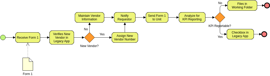
The Trigger: The process begins with an external document, Form 1. In BPMN, this is represented by a Start Event (the green circle) linked to a Message Start Event or simply a manual start triggered by the receipt of data.
The Core Loop: The architecture relies on a decision-making loop to determine if a vendor is “New” or “Existing.” This is the heart of the workflow, utilizing a split-merge structure common in process validation.
2. Step-by-Step Interpretation of the Example
Let’s walk through the process flow from left to right, interpreting the specific actions and logic gates.
Phase 1: Initiation and Verification
The process initiates when the system Receives Form 1. This task is supported by a data object (the paper icon), indicating that the form is a necessary input artifact. Immediately following receipt, the system performs a critical validation step: Verifies New Vendor in Legacy App. This represents a system interaction where the user or software checks the database to see if the entity already exists.
Phase 2: The First Decision Gateway (The “New Vendor?” Split)
Following the verification task, the flow hits a Exclusive Gateway (the orange diamond labeled “New Vendor?”). This is a standard XOR gateway, meaning the flow can only take one path at a time:
- The “No” Path: If the vendor is not new (i.e., they already exist), the process loops back to Maintain Vendor Information. This suggests a data update or administrative review is required for existing entities before moving forward.
- The “Yes” Path: If the vendor is confirmed as new, the system proceeds to Assign New Vendor Number. This is a critical step for data integrity, ensuring every new entity has a unique identifier.
Phase 3: Notification and Integration
Once the vendor number is assigned, the flow merges with the “No” path (if applicable) to reach the Notify Requestor task. This ensures the stakeholder is aware of the vendor’s status. The next logical step is Send Form 1 to Unit, transferring the data to the specific department responsible for further processing.
Phase 4: Analysis and Final Routing
The process concludes with a second decision point: Analyze for KPI Reporting. This leads to the final Exclusive Gateway labeled “KPI Reportable?”. This decision determines the system’s final state:
- Yes Path (Integrate): If the data is suitable for reporting, the system executes Checkbox in Legacy App. This represents a final confirmation action (like checking a box in a database) to mark the vendor as active. The process ends with a Terminating End Event (the red circle).
- No Path (Archive): If the vendor cannot be reported on (perhaps due to incomplete data or specific policy), the action is Files in Working Folder. This is an Intermediate Catching Event or a manual task that results in archiving the data, ending the process with a distinct termination point.
3. BPMN Key Concepts in Notation
To understand this diagram technically, one must recognize the specific notation elements used:
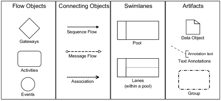
- Exclusive Gateway (Diamond): The orange diamonds represent logic branching. The labels “Yes” and “No” on the outgoing sequence flows are mandatory to define the conditions for the path taken. This ensures the “bracketing structure” is mathematically sound.
- Sequence Flow (Solid Arrow): The solid lines dictate the order of operations. Unlike a drawing tool where arrows are just visual guides, in BPMN 2.0, these are strictly defined execution paths.
- Data Object (Paper Icon): The “Form 1” icon represents a physical or digital artifact. It is linked to the “Receive Form 1” task via a dashed line, indicating an input/output relationship.
- Start and End Events: The green circle is the Start event, and the red circles are End events. The presence of multiple end events (one for success/integration, one for archiving) is a hallmark of complex process modeling.
4. Best Practices for Process Modeling
Based on the Vendor Management System example, here are the best practices for creating professional BPMN diagrams:
- Enforce Semantic Rules: Always use the correct gateway types. Do not use a diamond for a simple split if it requires a specific condition (use an Exclusive Gateway). Do not connect two events directly; there must be a task (activity) in between. This prevents invalid logic.
- Clear Labeling: Every sequence flow leaving a gateway must be labeled with its condition (e.g., “Yes”, “No”, “Approved”). Ambiguity in labeling leads to confusion during implementation.
- Round-Trip Engineering: In a professional environment, this diagram is not just a picture. It can be used to generate code skeletons or reverse-engineer the “Checkbox in Legacy App” function into a system requirement.
- Collaborative Versioning: By using a repository, teams can manage the “To-Be” analysis without file conflicts. If the “Verify” step changes, the whole team updates the single source of truth.
By treating BPMN as a model rather than a drawing, organizations can ensure their processes are not only visually clear but also logically robust and technically executable.